


– 90 –
Concealed Duct High Static Pressure
Installation Manual
Concealed Duct High Static Pressure
Installation Manual
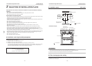
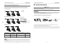
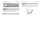
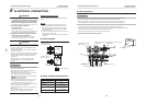
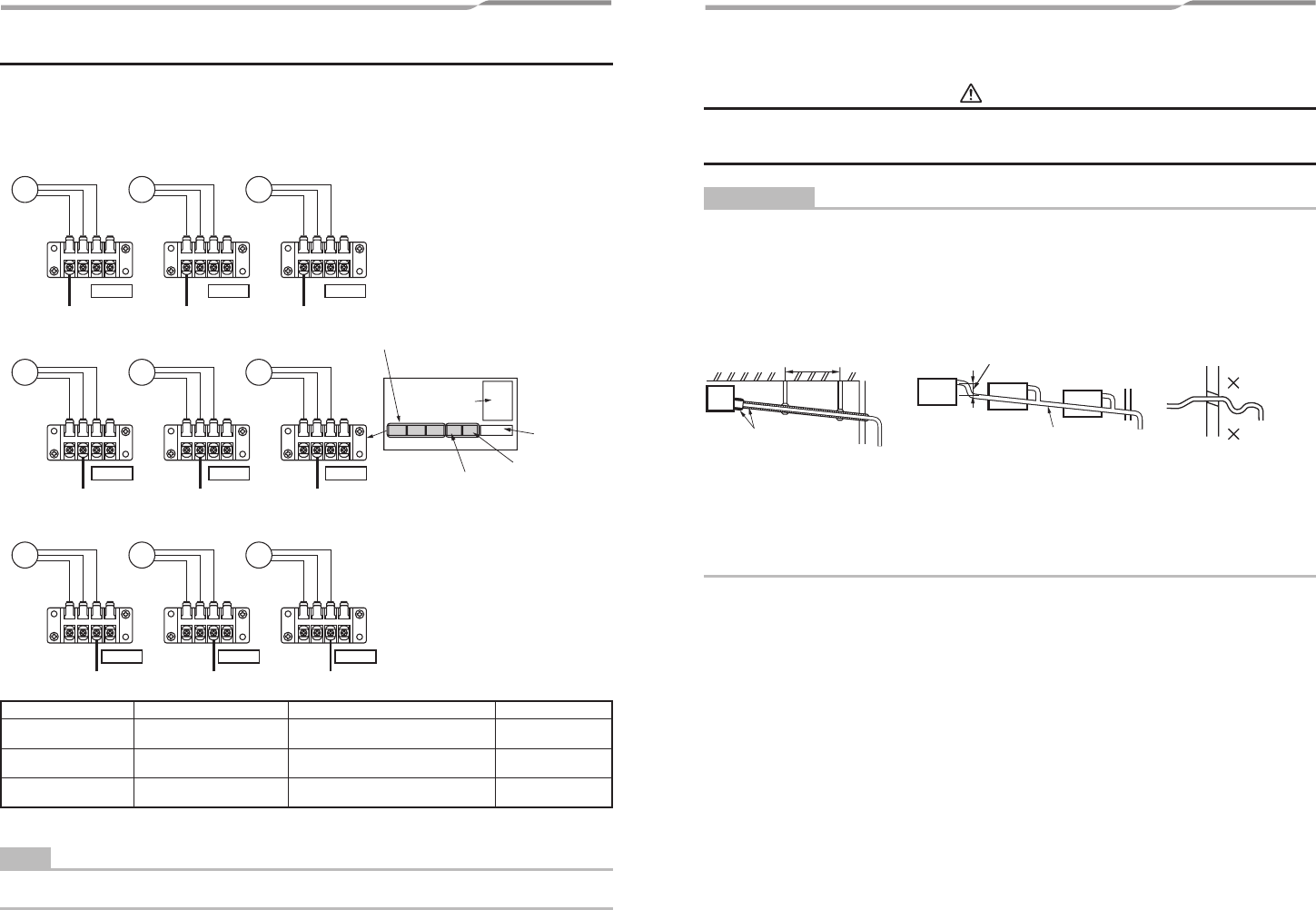
n Wire connection change of fan motor
This duct is composed of 3 fan motors.
To change external static pressure by duct resistance, connect the 3 connectors of the orange lead wires that are
connected to the underside of the fan tap changing terminal block to the same number (F1, F2 or F3) terminal.
The wires of the fan motor has been connected to (F2) [External static pressure 137Pa (14mmAq)] as factory default.
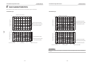
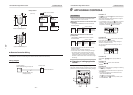
Low static pressure (F1)
F
1
F
2
F
3
F
4 F1 F2 F3 F4 F1 F2 F3 F4
YEL : Yellow
BLU : Blue
ORG : Orange
Fan motor Fan motor Fan motor
Fan motor Fan motor Fan motor
Fan motor Fan motor Fan motor
FAN3
FAN2
FAN1
F1 F2 F3 F4 F1 F2 F3 F4 F1 F2 F3 F4
Electrical control box
YEL
BLU
ORG
YEL
BLU
ORG
YEL
BLU
ORG
YEL
BLU
ORG
YEL
BLU
ORG
YEL
BLU
ORG
YEL
BLU
ORG
YEL
BLU
ORG
YEL
BLU
ORG
Fan tap changing terminal block
2P terminal block
3P terminal block
4P terminal block
Control
P.C. board
F1 F2 F3 F4 F1 F2 F3 F4 F1 F2 F3 F4
FM FM FM
FM FM FM
FM FM FM
ORG
ORG
ORG
ORG
ORG
ORG
ORG
ORG
ORG
FAN3
FAN2
FAN1
FAN3
FAN2
FAN1
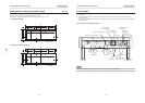
Standard (Middle) static pressure (F2)
High static pressure (F3)
∗ Do not use F4.
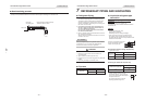
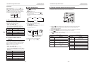
NOTE
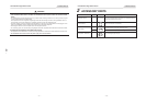
When the external static pressure is changed, write down the static pressure once change in the wiring diagram of the
indoor unit is made.
Terminal block No.
F1
F2
F3
Fan motor wiring
Yellow
Low static pressure
Blue
Middle static pressure
Orange
High static pressure
External static pressure Pa (mmAq)
69 (7)
137 (14)
196 (20)
Remarks
Factory default
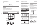
6 DRAIN PIPING WORK
CAUTION
Following the Installation Manual, perform the drain piping work that water is properly drained, and apply a heat
insulation not to cause a dew condensation.
Inappropriate piping work may cause the water leakage in the room and wet of furniture.
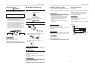
REQUIREMENT
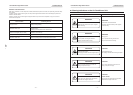
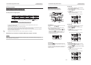
• The drain piping flows the natural drainage. Make sure to set the drain piping from the unit with descending slope of 1/50
to 1/100 and do not make up-down or trap in the midway.
• Set the horizontal pulling of the drain pipe to 20m or less. When drain piping is too long, attach the support bracket at
intervals of 1.5m to 2m to avoid the pipe becomes undulant as shown in figure below.
<Example for installation of the main piping (Incl. piping support)>
1.5 to 2 m
Descending slop of
1/50 to 1/100
Descending slop of
1/50 to 1/100
VP-30
As long as possible
Trap
Up-down bend
• Be sure to connect the drain pipe to the air conditioner with adhesive to avoid water leakage from the joint portion.
• Condensation may occur on the drain pipes including collective pipes.
All drain pipes must be wrapped with heat insulator to prevent dew condensation.
Especially a part where drain pipe is connected to the indoor unit must be firmly insulated with the provided heat insulator.
– 17 – – 18 –