


– 74 –
Concealed Duct High Static Pressure
Owner’s Manual
Concealed Duct High Static Pressure
Owner’s Manual
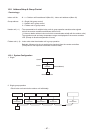
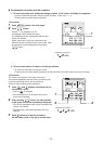
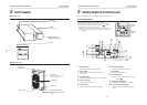
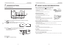
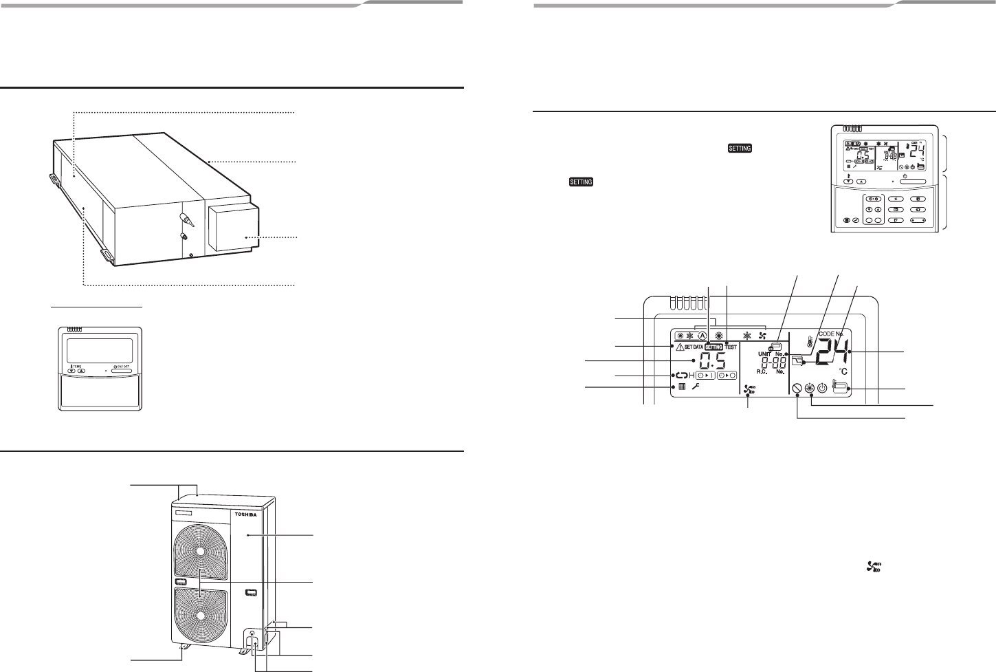
Air discharge
Connect a discharge duct.
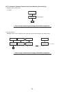
Remote controller
Separate sold part
Air intake
Connect a suction duct.
Drain pan
Electrical control box
The earth screw is provided in the
electrical control box.
Air intake
(Side and rear)
Front panel
There is an earth screw, valves,
and electric parts inside.
Air discharge
Pipe cover
Wire connection holes
Refrigerant pipe connection
holes
Mounting leg
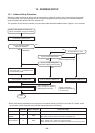
2 PART NAMES
n Indoor unit
n Outdoor unit
S
E
T
TIME
TIMER
S
E
T
TE
ST
FILTER
RE
S
E
T
TEMP.
CL
FAN
S
AV
E
S
WIN
G/
FI
X
VENT
M
O
D
E
O
N
/
O
F
F
U
NIT L
OU
VE
R
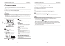
Display
section
Operation
section
1
8
6
4
2
3
5
7
13
15
14
9
12
11
10
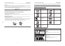
3 WIRED REMOTE CONTROLLER
This remote controller can control the operation of up to 8 indoor units.
n Display section
In the display illustration below all the icons are shown.
When the unit is in operation, only relevant icons will be displayed.
• When turning on the leak breaker at the first time,
flashes
on the display part of the remote controller.
• While this icon is flashing, the model is being automatically confirmed.
Wait till
icon has disappeared to use the remote controller.
1 Operation mode
The selected operation mode is displayed.
2 Error display
Displayed while the protective device works or a
error occurs.
3 SETTING display
Displayed during setup of the timer or other settings.
4 TEST run display
Displayed during a test run.
5 Timer display
When an error occurs, error code is displayed.
6 Timer mode display
The selected timer mode is displayed.
7 Filter display
Reminder to clean the air filter.
8 Fan speed display
Fan speed is not adjustable. It is fixed to High.
(HIGH)
9 Set temperature display
The selected set temperature is displayed.
10 Power saving mode display
Limits compressor speed (capacity) to save
energy.
– 7 – – 8 –