


– 59 –
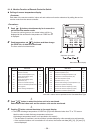
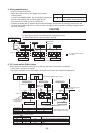
9-1-6. Monitor Function of Remote Controller Switch
n Calling of sensor temperature display
<Contents>
Each data of the remote controller, indoor unit and outdoor unit can be understood by calling the service
monitor mode from the remote controller.
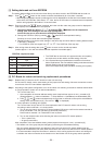
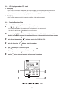
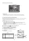
<Procedure>
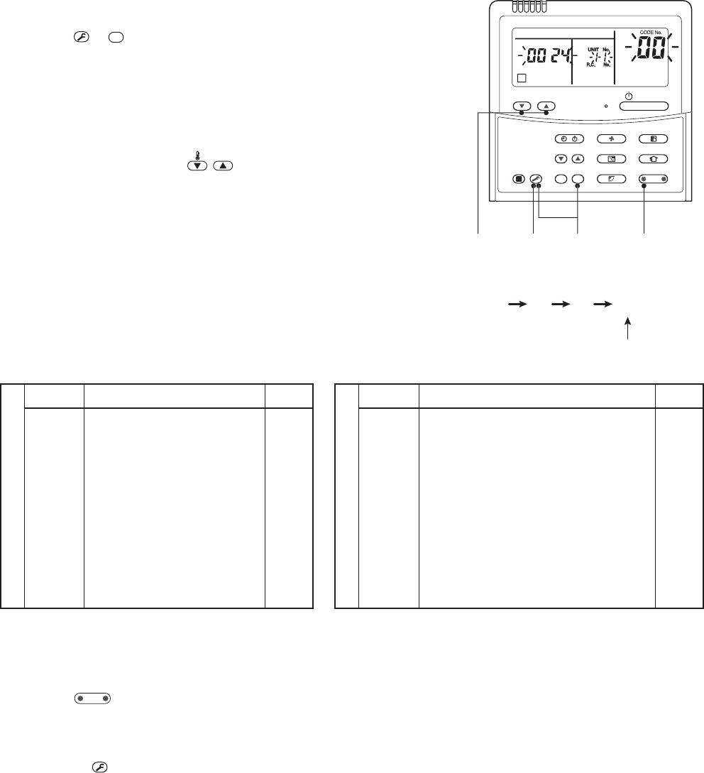
1 Push
TEST
+
CL
buttons simultaneously for 4 seconds to
call the service monitor mode.
The service monitor goes on, the master indoor unit No. is
displayed at first and then the temperature of CODE No.
is displayed.
ò
2 Push temperature set
TEMP.
buttons and then change
the CODE No. of data to be monitored.
The item code list is shown below.
<Operation procedure>
1 2 3 4
Returned to usual display
241 3
S
E
T
TIME
TIMER
S
E
T
TE
ST
FIL
TER
L
L
RE
S
E
T
TEMP
.
CL
FA
N
SA
VE
A
A
S
WIN
G/
FI
X
VENT
M
O
D
E
O
N
/
O
F
F
U
NI
T
LOUVER
T
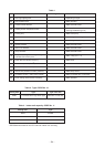
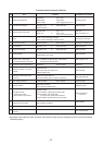
Indoor unit data
CODE No.
01
02
03
04
∗ 07
∗ F2
F3
∗ F8
Data name
Room temperature
(Remote controller)
Indoor suction temperature (TA)
Indoor heat exchanger (Coil)
temperature (TCJ)
Indoor heat exchanger (Coil)
temperature (TC)
Indoor fan revolution frequency
Indoor fan calculated operation time
Filter sign time
Indoor discharge temperature*1
Unit
°C
°C
°C
°C
rpm
×100h
×1h
°C
Outdoor unit data
CODE No.
60
61
62
63
65
6A
∗ 6D
∗ 70
∗ 72
∗ 73
F1
Data name
Outdoor heat exchanger (Coil) temperature (TE)
Outside temperature (TO)
Compressor discharge temperature (TD)
Compressor suction temperature (TS)
Heat sink temperature (THS)
Operation current (× 1/10)
Outdoor heat exchanger (Coil) temperature (TL)
Compressor operation frequency
Outdoor fan revolution frequency (Lower)
Outdoor fan revolution frequency (Upper)
Compressor calculated operation time
Unit
°C
°C
°C
°C
°C
A
°C
rps
rpm
rpm
×100h
Item with ∗ marks are not provided to the Concealed Duct Type.
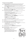
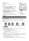
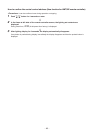
ò
3
Push
UNIT LOUVER
button to select the indoor unit to be monitored.
Each data of the indoor unit and its outdoor units can be monitored.
ò
4
Pushing
TEST
button returns the status to the usual display.
∗1 The indoor discharge temperature of CODE No. [F8] is the estimated value from TC or TCJ sensor.
Use this value to check discharge temperature at test run.
(A discharge temperature sensor is not provided to this model.)
• The data value of each item is not the real time, but value delayed by a few seconds to ten-odd seconds.
• If the combined outdoor unit is one before 2 or 3 series, the outdoor unit data [6D], [70], [72] and [73]
are not displayed.