


– 97 –
Concealed Duct High Static Pressure
Installation Manual
Concealed Duct High Static Pressure
Installation Manual
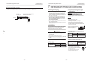
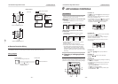
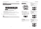
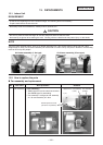
n Group control
Group control for system of multiple units
One remote controller can control up to 8 indoor units as a group.
t Group control in single system
Outdoor unit Outdoor unit Outdoor unit Outdoor unit Outdoor unit
Indoor unit
Remote controller
Indoor unit Indoor unit
Finish of address setup by power-ON
Indoor unit Indoor unit
(Max. 8 units)
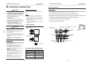
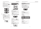
• For wiring procedure and wiring method of the individual line (Identical refrigerant line) system, refer to
“ELECTRICAL CONNECTION”.
• Wiring between lines is performed in the following procedure.
Connect the terminal block (A/B) of the indoor unit connected with a remote controller to the terminal blocks (A/B) of
the indoor units of other indoor units by wiring the inter-unit wire of the remote controller.
• When the power supply has been turned on, the automatic address setup starts and which indicates that address is
being set up flashes on the display part.
During setup of automatic address, the remote controller operation is not accepted.
Required time up to the finish of automatic addressing is approx. 5 minutes.
NOTE
In some cases, it is necessary to change the address manually after setup of the automatic address according to the
system configuration of the group control.
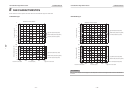
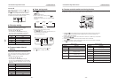
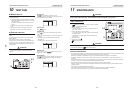
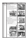
Procedure example 1
Manual address setup procedure
While the operation stops, change the setup.
(Be sure to stop the operation of the unit.)
2,61
7
3
-1,
4
5
6
-1,
-1,
7
3
-3,
4
-3,
3
-2,
4
-2,
5
-2
5
-3,
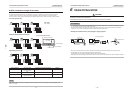
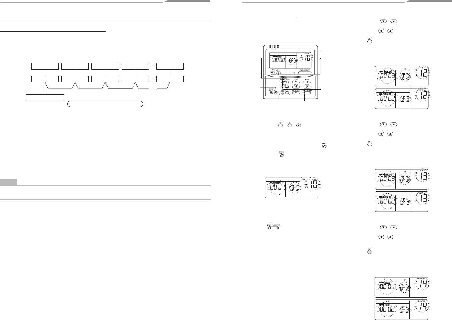
Procedure 1
Push simultaneously + + buttons for 4 seconds
or more.
After a while, the display part flashes as shown below.
Check the displayed CODE No. is [10].
• When the CODE No. is other than [10], push
button
to erase the display and repeat procedure from the first
step. (After pushing
button, operation of the remote
controller is not accepted for approx. 1 minute.)
(For a group control, No. of the firstly displayed indoor
unit becomes the header unit.)
(∗ Display changes according
to the model No. of indoor unit.)
Procedure 2
Every pushing button, the indoor UNIT No. in the
group control is displayed in order. Select the indoor unit of
which setup is changed.
In this time, the position of the indoor unit of which setup is
changed can be confirmed because fan of the selected
indoor unit operate.
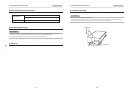
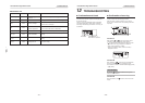
Procedure 3
1. Using TEMP. / buttons, specify CODE No.
[12]. (CODE No. [12]: Line address)
2. Using TIME
/ buttons, change the line address
from [3] to [2].
3. Push
button.
In this time, the setup finishes when the display
changes from flashing to lighting.
Indoor unit No. before setup change is displayed.
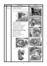
Procedure 4
1. Using TEMP. / buttons, specify CODE No.
[13]. (CODE No. [13]: Indoor address)
2. Using TIME
/ buttons, change the indoor
address from [3] to [2].
3. Push
button.
In this time, the setup finishes when the display
changes from flashing to lighting.
Indoor unit No. before setup change is displayed.
Procedure 5
1. Using TEMP. / buttons, specify CODE No.
[14]. (CODE No. [14]: Group address)
2. Using TIME
/ buttons, change the SET DATA
from [0001] to [0002]. (SET DATA [Header unit: 0001]
[Follower unit: 0002])
3. Push
button.
In this time, the setup finishes when the display
changes from flashing to lighting.
Indoor unit No. before setup change is displayed.
– 31 – – 32 –