


– 96 –
Concealed Duct High Static Pressure
Installation Manual
Concealed Duct High Static Pressure
Installation Manual
Procedure 6
When settings have been completed, push button to
determine the settings.
When
button is pushed, “SETTING” flashes and then
the display content disappears and the air conditioner
enters the normal stop mode. (While “SETTING” is flashing,
no operation of the remote controller is accepted.)
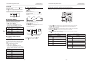
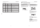
n Filter sign setting
According to the installation condition, the filter sign term
(Notification of filter cleaning) can be changed.
Follow to the basic operation procedure
(
1
→
2
→
3
→
4
→
5
→
6 ).
• For the CODE No. in Procedure
3, specify [01].
• For the [SET DATA] in Procedure
4, select the SET
DATA of filter sign term from the following table.
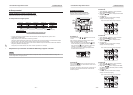
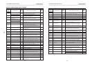
n To secure better effect of
heating
When it is difficult to obtain satisfactory heating due to
installation place of the indoor unit or structure of the
room, the detection temperature of heating can be raised.
Also use a circulator, etc. to circulate heat air near the
ceiling.
Follow to the basic operation procedure
(
1
→
2
→
3
→
4
→
5
→
6 ).
• For the CODE No. in Procedure
3, specify [06].
• For the set data in Procedure
4, select the SET DATA of
shift value of detection temperature to be set up from the
table below.
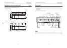
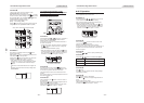
n Power saving mode
1. Push button for at least four seconds when the
air conditioner is not working.
flashes.
Indicates CODE No. “C2.”
2. Select an indoor unit to be set by pushing
(left side of the button).
Each time you push the button, unit numbers change
as follows:
UNIT No.
1-1
UNIT No.
1-2
UNIT No.
1-4
UNIT No.
1-3
The fan of the selected unit runs.
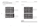
3. Adjust the power save setting by pushing
TIME
/ buttons.
Each push of the button changes the power level by 1%
within the range from 100% to 50%.
∗ The factory default is 75%.
Setting of power level
in power saving mode
4. Determine the setting by pushing button.
5. Push
button to complete the setting.
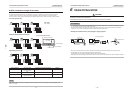
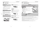
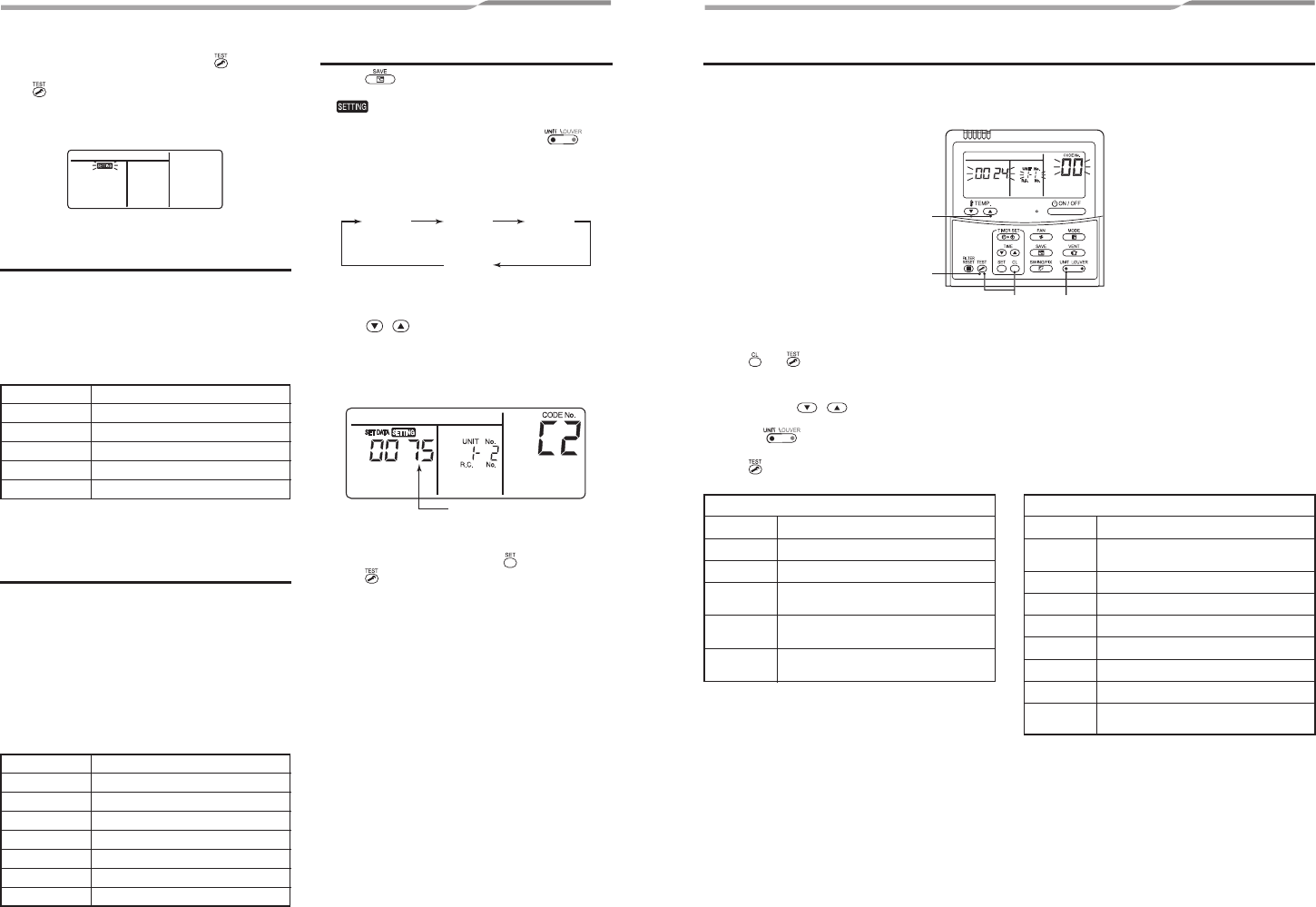
n Remote controller switch monitoring function
This function is available to call the service monitor mode from the remote controller during a test run to acquire
temperatures of sensors of the remote controller, indoor unit, and outdoor unit.
SET DATA
0000
0001
0002
0003
0004
Filter sign term
None
150H
2500H (Factory default)
5000H
10000H
SET DATA
0000
0001
0002
0003
0004
0005
0006
Detection temperature shift value
No shift
+1°C
+2°C (Factory default)
+3°C
+4°C
+5°C
+6°C
13
4
2
1. Push and buttons simultaneously for at least 4 seconds to call the service monitor mode.
The service monitor indicator lights up and the header indoor unit number is displayed first.
CODE No.
is also displayed.
2. Pushing TEMP.
/ buttons, select the number of sensor, etc. (CODE No.) to be monitored.
(See the following table.)
3. Pushing
(left side of the button), select an indoor unit to be monitored.
The sensor temperatures of indoor units and their outdoor unit in the control group are displayed.
4. Push
button to return to the normal display.
Indoor unit data
CODE No. Data name
01 Room temperature (remote controller)
02 Indoor unit intake air temperature (TA)
03
Indoor unit heat exchanger (coil)
temperature (TCJ)
04
Indoor unit heat exchanger (coil)
temperature (TC)
F3
Indoor unit fan cumulative operating hours
(× 1 h)
Outdoor unit data
CODE No. Data name
60
Outdoor unit heat exchanger (coil)
temperature (TE)
61 Outside air temperature (TO)
62 Compressor discharge temperature (TD)
63 Compressor suction temperature (TS)
64 —
65 Heatsink temperature (THS)
6A Operating current (× 1/10)
F1
Compressor cumulative operating hours
(× 100)
– 29 – – 30 –