


– 93 –
Concealed Duct High Static Pressure
Installation Manual
Concealed Duct High Static Pressure
Installation Manual
Tightening connection
CAUTION
Do not apply excessive torque. Otherwise, the
nut may crack depending on the conditions.
(Unit: N•m)
u Tightening torque of flare pipe connections
Pressure of R410A is higher than that of R22.
(Approx. 1.6 times)
Therefore, using a torque wrench, tighten the flare pipe
connecting sections which connect the indoor and
outdoor units of the specified tightening torque.
Incorrect connections may cause not only a gas leak,
but also a trouble of the refrigeration cycle.
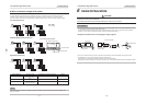
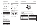
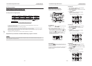
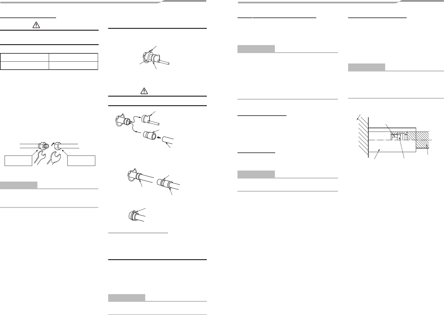
Align the centres of the connecting pipes and tighten
the flare nut as far as possible with your fingers.
Then tighten the nut with a spanner and torque wrench
as shown in the figure.
Externally
threaded side
Internally
threaded side
Half union Flare nut
Use a wrench to secure. Use a torque wrench to tighten.
REQUIREMENT
Tightening with an excessive torque may crack the nut
depending on installation conditions.
Tighten the nut within the specified tightening torque.
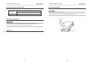
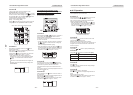
n Gas side refrigerant pipe
connection
• Turn up the pipe heat insulator to the unit side.
• Wrap the pipe with wet cloth.
Turn up pipe heat insulator
Remove the all brazed part.
Wet cloth
• Remove the cup on the gas side piping by using a
brazing machine.
CAUTION
Do not burn the pipe heat insulator.
Remove the cap.
Connection pipe
Locally procured
Ø28.6 mm
Attached joint part
• Braze the attached joint part to the gas side piping and
braze the connection piping to the joint part.
Braze all around
Brazing
Brazing
• Turn back the pipe heat insulator and tie up with a
banding band.
Tie up with a banding band.
Piping with outdoor unit
• For details of installation, refer to the Installation Manual
of the outdoor unit.
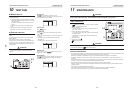
n Evacuation
Using a vacuum pump, perform vacuuming from the
charge port of valve of the outdoor unit.
For details, follow to the Installation Manual attached to the
outdoor unit.
• Never use the refrigerant sealed in the outdoor unit for
evacuation.
REQUIREMENT
For the tools such as charge hose, etc., use those
manufactured exclusively for R410A.
Outer dia. of copper pipe
12.7 mm (dia.)
Tightening torque
50 to 62 (5.0 to 6.2 kgf•m)
Refrigerant amount to be added
For addition of the refrigerant, add refrigerant “R410A”
referring to the attached Installation Manual of outdoor unit.
Be sure to use a scale to charge the refrigerant of specified
amount.
REQUIREMENT
• Charging an excessive or too little amount of refrigerant
causes a trouble of the compressor.
Be sure to charge the refrigerant of specified amount.
• A personnel who charged the refrigerant should write
down the pipe length and the added refrigerant amount in
the nameplate attached to the service panel of the
outdoor unit.
It is necessary to fix the compressor and refrigeration
cycle malfunction.
Open the valve fully
Open the valve of the outdoor unit fully.
A 4mm-hexagonal wrench is required for opening the valve.
For details, refer to the Installation Manual attached to the
outdoor unit.
Gas leak check
Check with a leak detector or soap water whether gas leaks
or not, from the pipe connecting section or cap of the valve.
REQUIREMENT
Use a leak detector manufactured exclusively for HFC
refrigerant (R410A, R134a, etc.).
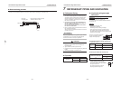
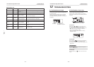
Heat insulation process
Apply heat insulation for the pipes separately at liquid
side and gas side.
For the heat insulation to the pipes at gas side, be sure to
use the material with heat-resisting temperature 120°C or
higher.
Using the attached heat insulation material, apply the
heat insulation to the pipe connecting section of the
indoor unit securely without gap.
REQUIREMENT
• Apply the heat insulation to the pipe connecting section
of the indoor unit securely up to the root without
exposure of the pipe.
(The pipe exposed to the outside causes water leak.)
• Wrap heat insulator with its slits facing up (ceiling side).
Indoor unit
Union
Heat insulation
(Accessory)
Flare nut
Heat insulator
of the pipe
– 23 – – 24 –