


– 34 –
13
4
2
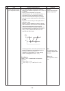
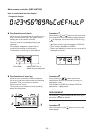
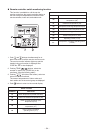
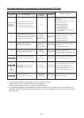
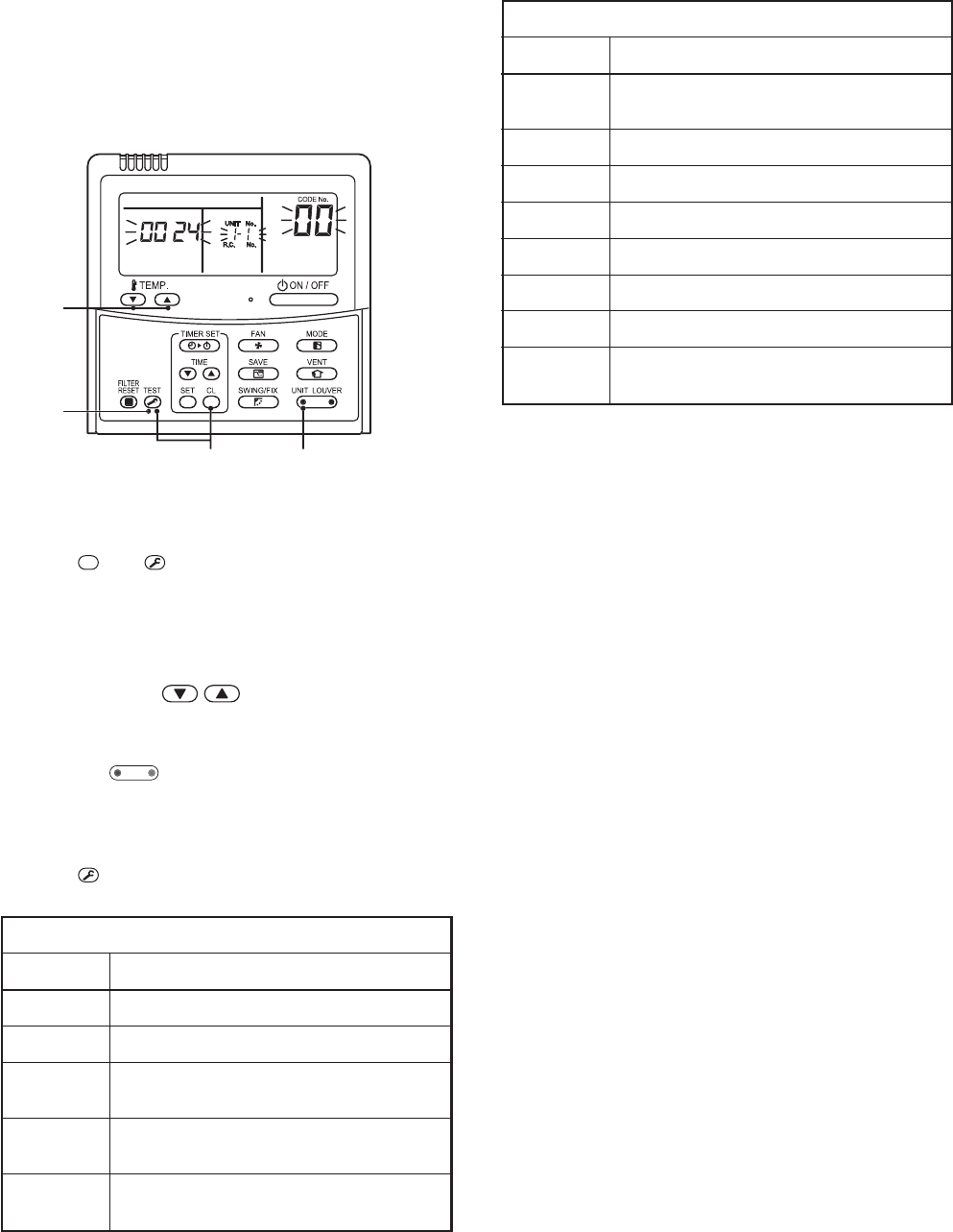
n Remote controller switch monitoring function
This function is available to call the service
monitor mode from the remote controller during a
test run to acquire temperatures of sensors of the
remote controller, indoor unit, and outdoor unit.
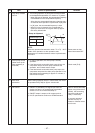
1. Push
CL
and
TEST
buttons simultaneously for at
least 4 seconds to call the service monitor mode.
The service monitor indicator lights up and the
header indoor unit number is displayed first.
CODE No. is also displayed.
2. Pushing TEMP. buttons, select the
number of sensor, etc. (CODE No.) to be
monitored. (See the following table.)
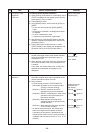
3. Pushing
U
NIT L
OU
VE
R
(left side of the button), select an
indoor unit to be monitored.
The sensor temperatures of indoor units and
their outdoor unit in the control group are displayed.
4. Push
TEST
button to return to the normal display.
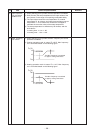
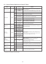
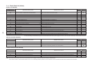
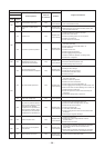
Indoor unit data
CODE No. Data name
01 Room temperature (remote controller)
02 Indoor unit intake air temperature (TA)
03
Indoor unit heat exchanger (coil)
temperature (TCJ)
04
Indoor unit heat exchanger (coil)
temperature (TC)
F3
Indoor unit fan cumulative
operating hours (x1 h)
Outdoor unit data
CODE No. Data name
60
Outdoor unit heat exchanger (coil)
temperature (TE)
61 Outside air temperature (TO)
62 Compressor discharge temperature (TD)
63 Compressor suction temperature (TS)
64 —
65 Heatsink temperature (THS)
6A Operating current (x1/10)
F1
Compressor cumulative operating hours
(x100h)