


– 144 –
No.
8
Part name
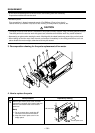
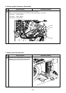
Replacement of
electric parts
IPDU P.C. board
Procedure
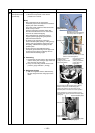
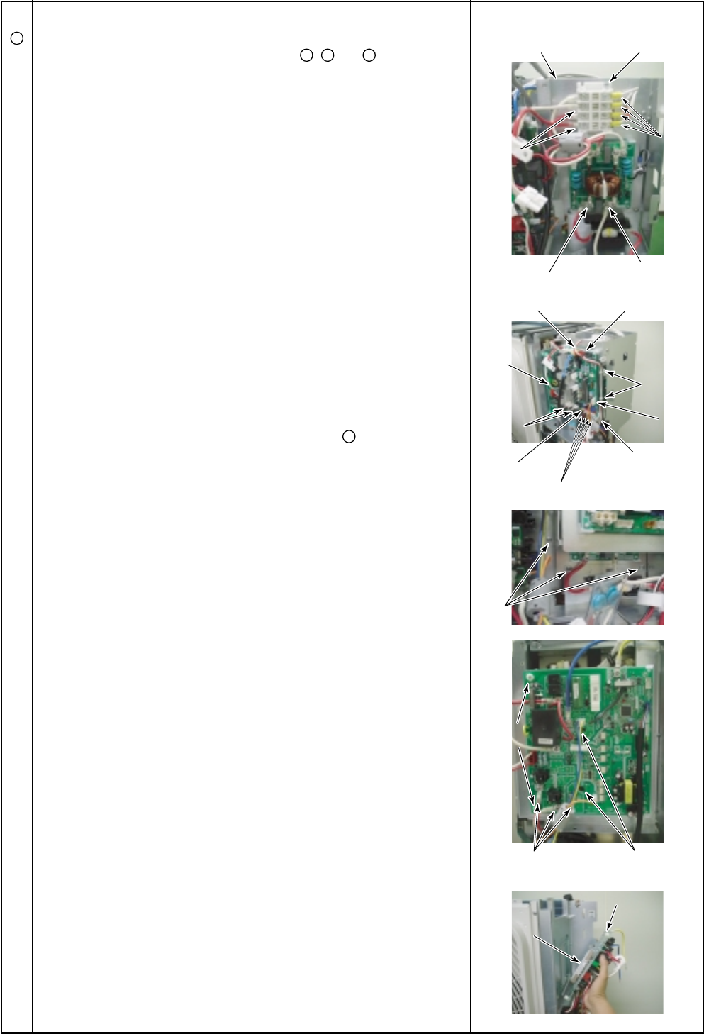
1. Detachment
1) Carry out works of 1 of
1
,
3
and
4
.
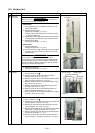
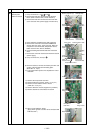
2) Remove the lead wire connected to the terminal
block. (IPDU crossover wire, reactor lead wire)
3) Remove the lead wire connected to the noise filter.
(Fuse crossover wire, power supply crossover wire)
Remarks
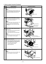
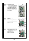
4) Close CDB part. (Tentative fixing with supporter)
5) Remove the connector connected to CDB board.
(Serial, lower fan motor, 4-way valve coil, PMV coil,
compressor case thermostat, temperature sensor,
IPDU crossover wire, DC15V, DC280V)
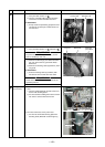
6) Cut the bundling band which binds the serial lead
wires.
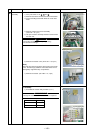
7) Remove the connector connected to IPDU P.C. board.
(Power supply)
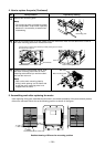
8) Carry out works of 5) and 8) of
7
.
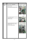
9) Remove screws to connect the electric parts box and
screws of the terminal block mounting plate.
(BT2T Ø4 × 6, 3 pcs.)
10) Pull up the electric parts box to separate the unit at
CDB side.
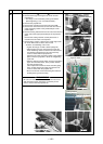
11) Remove the compressor lead wire.
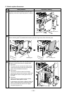
12) Remove IGPT fixing screws. (B Ø4 × 15, 2 pcs.)
13) Remove screws which fix the P.C. board.
(TT2P Ø3 × 18, 2 pcs.)
14) Remove IPDU P.C. board. (Supporter: 2 positions)
15) Remove lead wires connected to P.C. board.
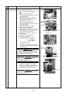
16) Mount a new IPDU P.C. board.
(Apply silicon grease to surface to be contacted with
IGBT heat sink.)
Electric parts box (A) Terminal block
Reactor
Reactor
lead wire
lead wire
IPDU
IPDU
crossover wire
crossover wire
Reactor
lead wire
IPDU
crossover wire
Fuse
crossover wire
Power supply
crossover wire
4-way valve
Power
Power
supply
supply
Bundling
Bundling
band
band
Compressor
case thermostat
Temperature sensor
Screws
Screws
Screws
P.C. board
P.C. board
fixing screws
fixing screws
P.C. board
fixing screws
Compressor
lead wires
IGBT
fixing screws
IPDU
crossover wire
PMV
PMV
Bundling
band
PMV
Lower
Lower
fan motor
fan motor
Power
supply
Lower
fan motor
Serial crossover wire
Silicon grease
Silicon grease
Silicon grease
IGBT
IGBT
IGBT