


110
Screw Screw
Screw Screw
Heat sink
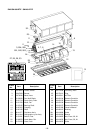
P.C. board fixing hooks (5 positions)
IPDU P.C. board
Screw
Screw
IPDU P.C. board Heat sink cover
No.
Part name
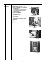
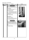
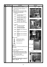
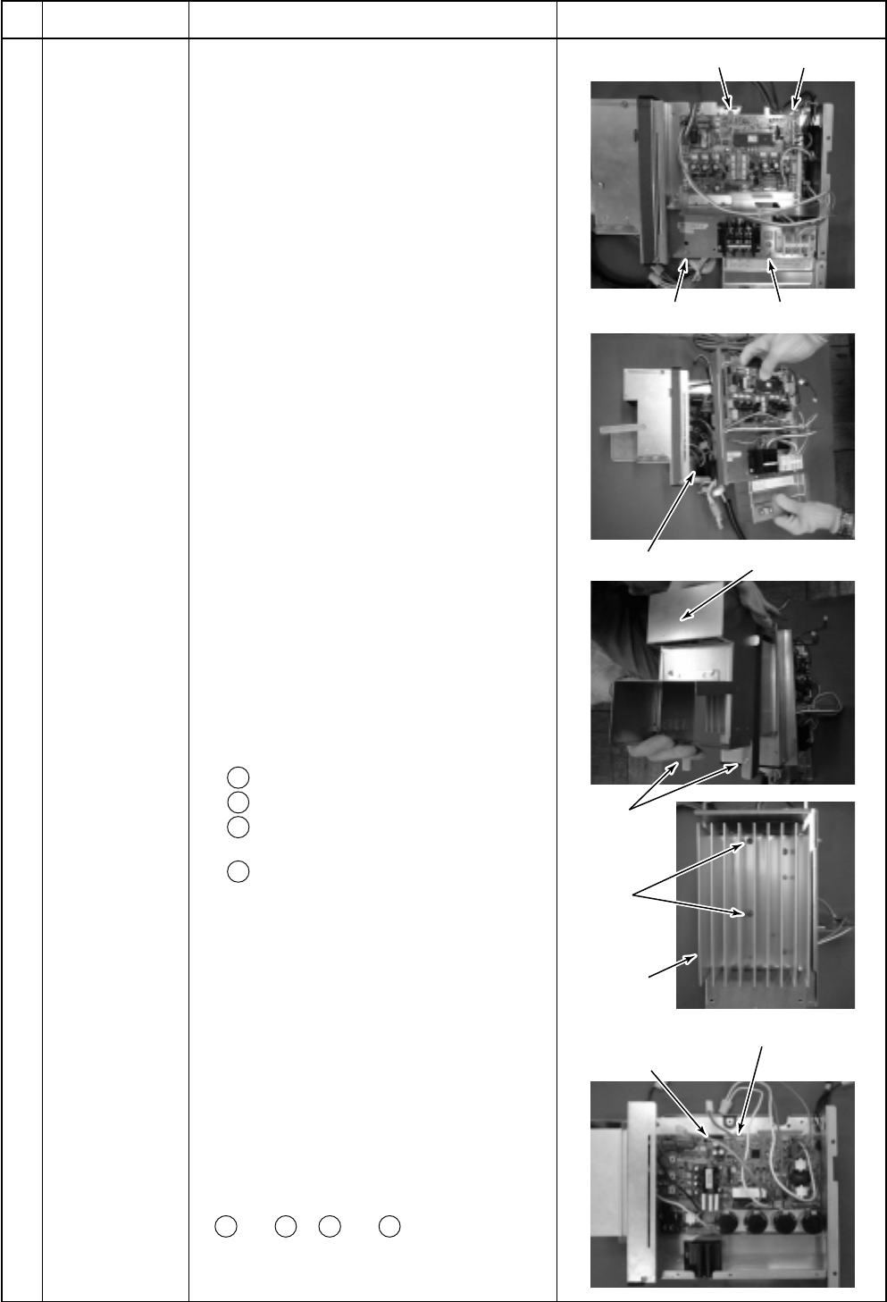
IPDU P.C. board
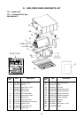
Procedure
1) Perform the works in and .
2) Take off screws of the inverter assembly
to separate the inverter assembly.
(M4 × 8, 4 pcs)
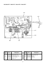
3) Remove the connectors and the lead
wires which are connected from IPDU
P.C. board to the other parts.
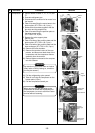
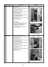
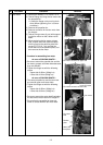
1. Connector
CN04: Connection with cycle P.C.
board (3P: White)
CN05: Connection with cycle P.C.
board (2P: White) *(Note 1)
CN06: Connection with cycle P.C.
board (5P: White)
CN13: Connection with cycle P.C.
board (5P: Red) *(Note 1)
CN600: Heat sink sensor (2P: Black)
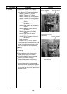
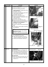
2. Lead wire
CN01: Connection with power
terminal block (Red)
CN02: Connection with power
terminal block (White)
CN03: Connection with inverter box
(Black)
CN09: Connection with compressor
(Red)
CN10: Connection with compressor
(White)
CN11: Connection with compressor
(Black)
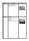
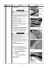
Rectifier diode
+ : Red lead wire *Note 2
– : White lead wire *Note 2
~ : Orange lead wire
(Top)
~ : Brown lead wire
(Bottom)
*(Note 1)
Remove the connectors by releasing lock of
the housing.
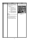
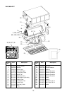
4) Remove the heat sink cover.
(M4 × 8, 2pcs)
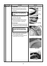
5) Take off two screws which fix the heat
sink and IGBT and also take off support
hooks of the P.C. board (5 positions) to
remove IPDU P.C. board.
6) Mount a new IPDU P.C. board.
*(Note 2)
The rectifier diode has polarity, so be careful
to + and – . If + and – are mistaken, a
trouble is caused.
Remarks