108
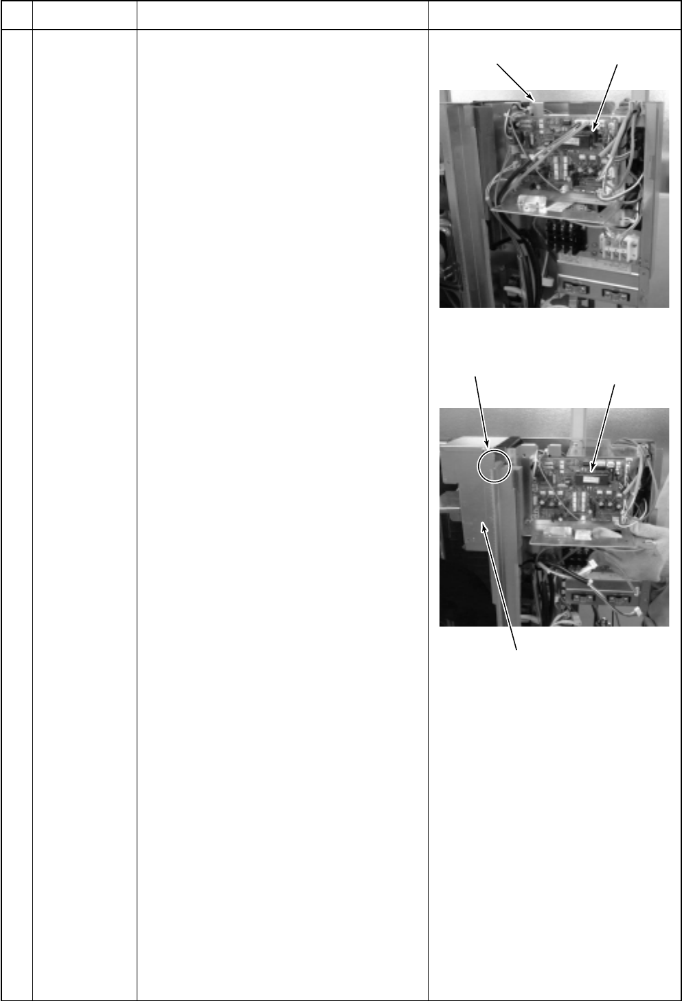
Inverter assembly
Inverter assembly
Heat sink cover
Hooks of heat sink cover
(2 positions)
Cycle P.C. board
No.
Part name
Inverter
assembly
Procedure
1) Perform the works in 1 of and .
2) Remove connectors which are connected
from the cycle P.C. board to other parts.
CN600: TD sensor (3P: White)
CN601: TO sensor (2P: White)
CN604: TE sensor (2P: White) *(Note 1)
CN605: TS sensor (3P: White) *(Note 1)
CN301: Upper outdoor fan (3P: White)
*(Note 1)
CN300: Detection of upper position
(5P: White)
CN303: Lower outdoor fan (3P: White)
*(Note 1)
CN302: Detection of lower position
(5P: White)
CN500: Case thermo. (2P: White)
*(Note 1)
CN700: 4-way valve (3P: Yellow)
*(Note 1)
CN702: PMV (Pulse Motor Valve) coil
(6P: White)
Relay connector:
Reactor 2 pcs. (3P: White) *(Note 1)
Compressor lead: Remove terminal cover
of the compressor, and remove the lead
wire from terminal of the compressor.
*(Note 1)
Remove the connectors by releasing lock of
the housing.
3) Remove various lead wires from the
holder at upper part of the inverter.
4) Cut off tie lap which fixes various lead
wires to the inverter assembly.
5) Lift up the hook (upper left) with the
partition plate upward just removing.
* Caution to mount the inverter assembly
Mount the inverter assembly to the partition
plate so that hooks of the heat sink cover
do not come near the partition plate but also
near the fan side.
Remarks


