


31
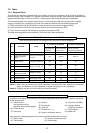
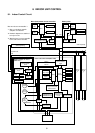
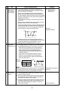
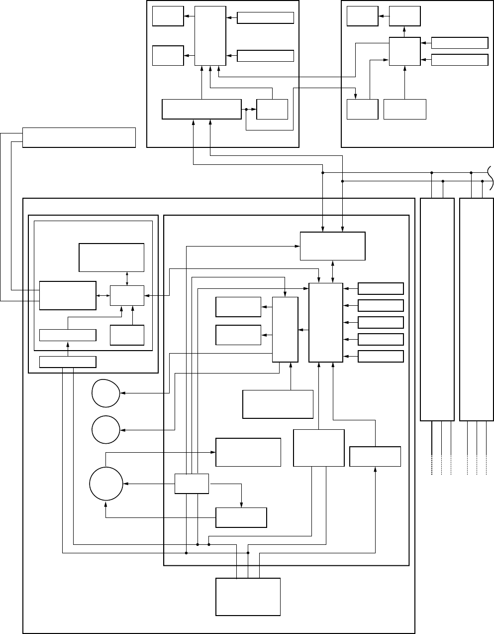
8. INDOOR UNIT CONTROL
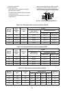
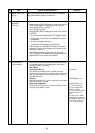
8-1. Indoor Control Circuit
Network adapter (Sold separatrly)
Indoor control P.C. board (MCC-1402)
CPU
EEPROM
#1
#3
AB
Indoor unit
Main (Sub) master remote controller
Run Warning
Ready Thermo. ON
Cool Heat Fan
Outside output
Driver
Remote controller
communication circuit
CPU
H8/3039
Louver
motor
Drain
pump
Indoor
fan
motor
Transformer
Outdoor unit
123
123
DC5V
CPU
LCD
driver
Function setup
Key switch
Function setup
Key switch
Weekly timer
Secondary
battery
Power
circuit
DC5V
*
3
CN2
CN1
123
Outdoor
unit
Same as
the left
*
2
#2
ABAB
123
Outdoor
unit
Same as
the left
*
2
Max. 8 units are connectable.*1
*1 Max. 7 units when network
adapters are attached
*2 Network adapters are attached
to only one unit.
*3 Weekly timer is not connectable
to the sub remote controller.
Network adapter P.C. board
(MCC-1401)
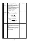
Power circuit
DC5V
Sold separatrly Sold separatrly
DC280V
X
Y
DC20V
DC12V
DC5V
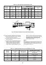
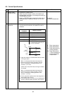
Display
LCD
Display
LCD
Display
LED
Power
circuit
CPU
H8/3687
Humidifier
relay output
Heater relay
output
Switch
setup
AI NET
communication
circuit
Remote controller
communication
circuit
Remote controller
communication
circuit
TA sensor
TC sensor
TCJ sensor
Float input
Serialsend/
receive circuit
AC
synchronous
signal input
circuit
Power
circuit
CPU
TMP88CH47FG
(TMP88PH47FG)
Fan motor
control circuit
Central control remote controller
(
Sold separatrly
)