–31–
SMMS-i
Installation Manual
SMMS-i
Installation Manual
11 TROUBLESHOOTING
In addition to the CODE No. on the remote controller of an indoor unit, you can diagnose failure type of an outdoor unit by
checking the 7-segment display on the interface P.C. board.
Use the function for various checks.
Set every dip switch to OFF after checking.
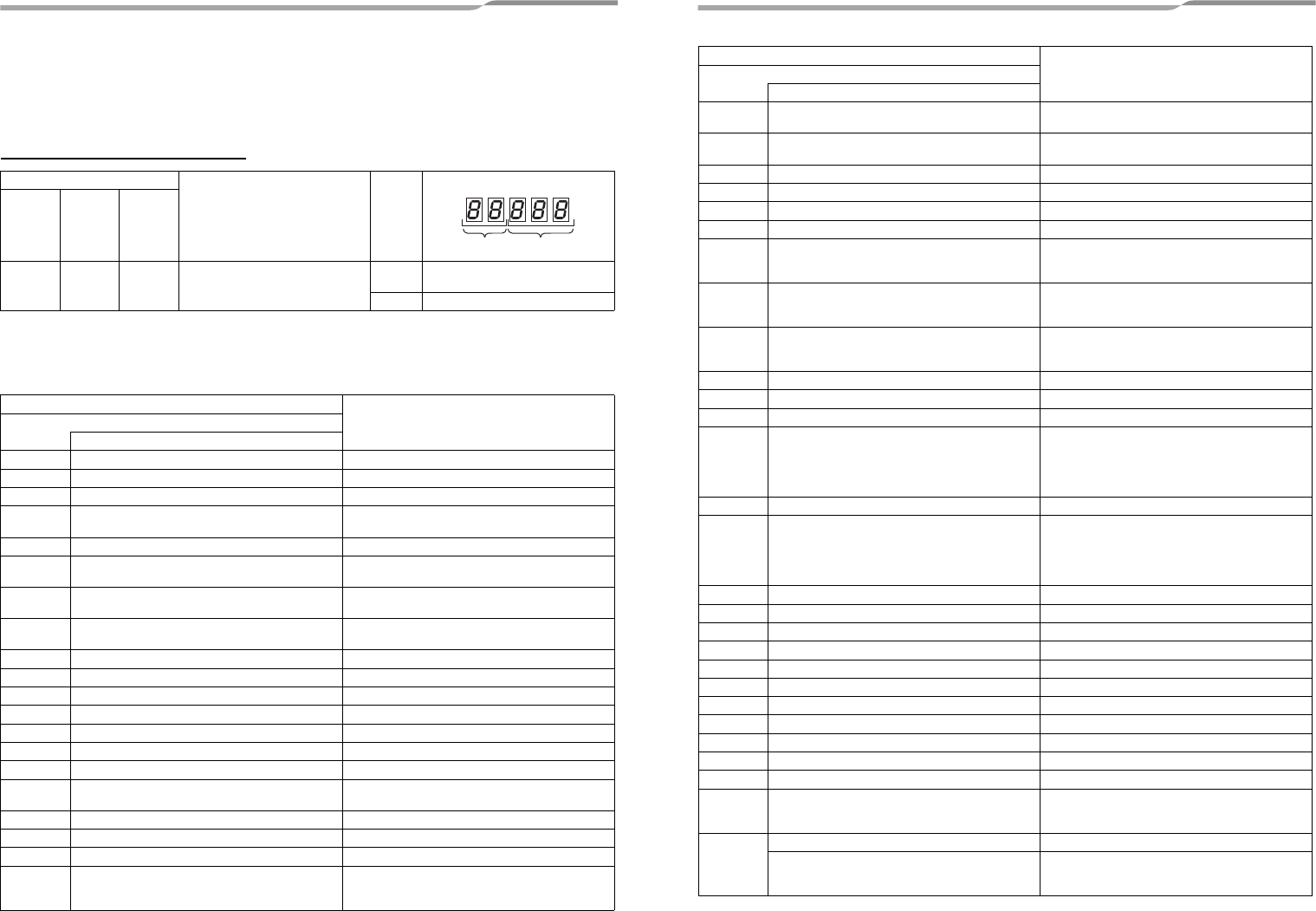
7-Segment display and check code
* If a check code has an auxiliary code, the display indicates the check code for three seconds and the auxiliary
code for one second alternately.
Check code (indicated on the 7-segment display on the outdoor unit)
Indicated when SW01 = [1], SW02 = [1], and SW03 = [1].
Rotary switch setting value
Indication LED
SW01 SW02 SW03
1 1 1 Outdoor unit check code
A
Outdoor unit number
(U
1 to U4)
B Check code display*
Check code
Check code nameIndication on 7-segment display on the outdoor unit
Auxiliary code
E06 Number of indoor units which received normally Decrease of number of indoor units
E07 — Indoor/outdoor communication circuit error
E08 Duplicated indoor addresses Duplication of indoor addresses.
E12
01: Communication between indoor and outdoor units
02: Communication between outdoor units
Automatic addressing start error
E15 — No indoor unit during automatic addressing
E16
00: Capacity over
01~: Number of connected units
Capacity over / number of connected indoor units
E19
00: Header is nothing
02: 2 or more header units
Number of header outdoor unit error
E20
01: Other line indoor connected
02: Other line indoor connected
Other lines connected during automatic addressing
E23 — Sending error between outdoor units communication
E25 — Duplicated follower outdoor address set up
E26 Number of outdoor units which received normally Decrease of connected outdoor units
E28 Detected outdoor Follower outdoor unit error
E31 IPDU quantity information
(*1)
IPDU communication error
F04 — TD1 sensor error
F05 — TD2 sensor error
F06
01: TE1 sensor
02: TE2 sensor
TE1 sensor error
TE2 sensor error
F07 — TL sensor error
F08 — TO sensor error
F12 — TS1 sensor error
F13
01: Compressor 1
02: Compressor 2
03: Compressor 3
TH (Heat sink) sensor error
D600
AB
D601 D602 D603 D604
F15 —
Outdoor temp. sensor miswiring
Outdoor pressure sensor miswiring (TE1, TL)
F16 —
Outdoor temp. sensor miswiring
Outdoor pressure sensor miswiring (Pd, Ps)
F22 — TD3 sensor error
F23 — Ps sensor error
F24 — Pd sensor error
F31 — Outdoor EEPROM error
H01
01: Compressor 1
02: Compressor 2
03: Compressor 3
Compressor breaking down
H02
01: Compressor 1
02: Compressor 2
03: Compressor 3
Compressor error (Locked)
H03
01: Compressor 1
02: Compressor 2
03: Compressor 3
Current detection circuit error
H05 — TD1 sensor miswiring
H06 — Low pressure proctive operation
H07 — Oil level down detection
H08
01: TK1 sensor error
02: TK2 sensor error
03: TK3 sensor error
04: TK4 sensor error
05: TK5 sensor error
Temperature sensor error for oil level
H15 — TD2 sensor miswiring
H16
01: TK1 oil circuit error
02: TK2 oil circuit error
03: TK3 oil circuit error
04: TK4 oil circuit error
05: TK5 oil circuit error
Oil level detector circuit error
H25 — TD3 sensor miswiring
L04 — Outdoor system address duplication
L06 Number of prior indoor units Duplication of indoor units with priority
L08 — Indoor unit group/address unset
L10 — Outdoor unit capacity unset.
L17 — Mismatch of the outdoor unit model
L28 — Outdoor connected quantity over
L29 IPDU number information
(*1)
IPDU quantity error
L30 Detected indoor unit address External interlock of indoor unit
L31 — Other compressor errors
P03 — Discharge temperature TD1 error
P04
01: Compressor 1
02: Compressor 2
03: Compressor 3
High-pressure SW system operation
P05
00: Phase missing/power failure detection
01: Compressor 1
02: Compressor 2
03: Compressor 3
Inverter DC voltage error (on compressor)
Check code
Check code nameIndication on 7-segment display on the outdoor unit
Auxiliary code
61-EN 62-EN
+00EH99871699_01EN.book Page 31 Thursday, August 26, 2010 4:41 PM


