


7
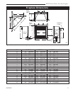
RDVN Series Direct Vent Gas Fireplace
20007628
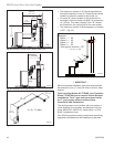
A hearth is not mandatory but is recommended for
aesthetic purposes. We recommend a noncombustible
hearth which projects out 12” (305 mm) or more from
the front of the fireplace.
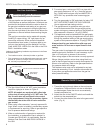
Cold climate installation recommendation:
When installing this unit against a
non-insulated exterior wall or chase,
it is mandatory that the outer walls
be insulated to conform to applicable
insulation codes.
NOTE: Never allow vapor barrier to contact the
outer casing of this fireplace or venting.
Hearth
Final Finishing
Noncombustible materials such as brick or tile may be
extended over the edges of the face of the appliance.
DO NOT cover any vent or grille panels.
If a Trim Kit is going to be installed on the fireplace, the
brick or tile will have to be installed flush with the edges
of the appliance.
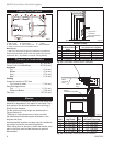
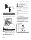
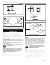
Framing and Finishing
1. Choose the unit location.
2. Place the unit into position and secure it to the floor
with 1¹⁄₂” (38 mm) screws, or nails. The holes to
secure the unit to the floor are located just behind
the access door grille on the left and right side of the
unit.
3. Frame in the fireplace with a header across the top.
It is important to allow for the finished wall face when
setting the depth of the frame.
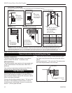
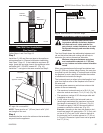
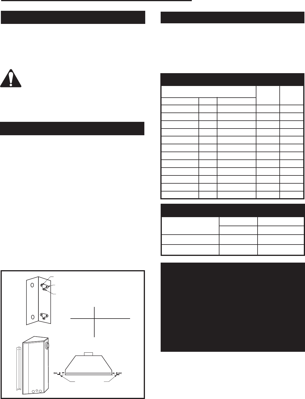
4. Attach the fireplace to the frame using the adjust
-
able frame drywall strips (located behind the access
door for shipping). Preset the depth to suit the facing
material of the wall. The strips are adjustable to 1/2”
(13 mm), 5/8” (16 mm) or 3/4” (19 mm). (Fig. 4)
5. Screw through the slotted holes in the drywall strip
and into the pre-drilled holes in the fireplace side.
Measure from the face of the fireplace to the face of
the drywall strip to confirm the final depth.
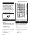
High Elevations
Input ratings are shown in BTU per hour and are
certified without deration for elevations up to
4,500 feet (1,370 m) above sea level.
For elevations above 4,500 feet (1,370 m) in USA,
installations must be in accordance with the cur-
rent ANSI Z223.1/NFPA 54 and/or local codes hav-
ing jurisdiction.
In Canada, please consult provincial and/or local
authorities having jurisdiction for installations at
elevations above 4,500 feet (1,370 m).
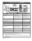
Natural LP (Propane)
Inlet Minimum 4.5” w.c. 10.8” w.c.
Inlet Maximum 14.0” w.c. 14.0” w.c.
Manifold Pressure 3.5” w.c. 10.0” w.c.
Gas Inlet and Manifold Pressures
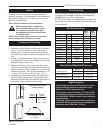
FP1023
side nailing flange
1/27/00 djt
C
A
B
Fig. 4 Nailing flanges.
FP1023
Adjustable
1/2”, 5/8” &
3/4” Spacing
Adjustable Drywall Strip
(Nailing Flange)
Screw Drywall
Position Depths
A 1/2” / 13mm
B 5/8” / 16mm
C 3/4” / 19mm
Gas Specifications
Max. Min.
Input Input
Model Fuel Gas Control BTU/h BTU/h
33RDVN Nat Millivolt 18,000 13,000
33RDVP Prop Millivolt 18,000 13,000
33RDVDSN Nat 120 V 18,000 n/a
33RDVDSP Prop 120 V 18,000 n/a
36RDVN Nat Millivolt 20,000 13,000
36RDVP Prop Millivolt 20,000 13,000
36RDVDSN Nat 120 V 20,000 n/a
36RDVDSP Prop 120 V 20,000 n/a
39RDVN Nat Millivolt 22,000 15,000
39RDVP Prop Millivolt 22,000 15,000
39RDVDSN Nat 120 V 22,000 n/a
39RDVDSP Prop 120 V 22,000 n/a