


39
RDVN Series Direct Vent Gas Fireplace
20007628
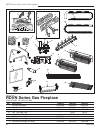
Bay window kits are available for the 33TDVN/33RDVN,
36TDVN/36RDVN & 39TDVN/39RDVN model
appliances.
When fitting the Bay Window Kits the
original window frame assembly must
remain in place. The Bay Window kit will fit
over the existing window frame assembly.
Installation
1. Remove the existing bottom louvre assembly
complete with the hinges.
2. Remove the top louvre assembly.
3. Assemble the Bay Window Kit according to the
instructions supplied with the kit.
4. Place the 2 pieces of ceramic refractory along the
base of the bay window. (Fig. 61)
5. Hang the Bay Window Assembly over the existing
window frame assembly.
6. Re-install the upper louvre assembly.
Do not remove the existing window frame
assembly.
Decorative Bay Windows
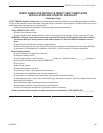
The fireplace, when installed, must be
electrically connected and grounded in
accordance with local codes or, in the
absence of local codes, with the current
CSA C22.1 Canadian Electric Code.
For USA installations follow the local
codes and the national electrical code
ANSI/NFPA No. 70.
Should this fan require servicing or repair
the power supply must be disconnected.
For rewiring of any replacement parts refer
to Figure 59.
Any electrical re-wiring of this fan must be
done by a licensed electrician.
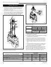
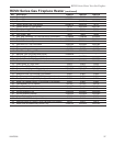
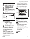
Wiring Instructions
Black
White
Ground
FP394
WIRING DIAGRAM
11/20/96
Fan
Temperature Sensor
Speed Control
FP1025
Fig. 59 FK24 fan wiring.
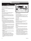
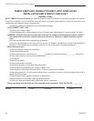
Ceramic refractory panels are available in kit form for
the RDV/TDV series appliances.
5. Place the rear refractory panel in place.
6. Slide the side refractory panels into place to hold
the rear panel secure. Adjust the top adjustable tabs
to hold the side panel against the firebox wall and
secure the tab. Repeat the procedure on the other
side.
7. Replace the logs and window frame assembly.
For esthetic purposes we recommend
lining up the horizontal mortar lines.
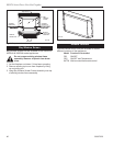
Ceramic Refractory Kits
Take care when handling the refractory
panels as they are fragile until held in
place and supported.
NOTE: The bottom pieces supplied in ceramic
refractory kit are not used on these fireplaces.
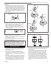
Installation, refer to Figure 60
1. Remove the front window frame assembly.
2. Remove the logs.
3. Place the lower supports for the side refractory
panels on the base of the firebox. Place each
support so the slotted hole fits over the forward
screw head along the edge of the base.
4. Loosely attach the top adjustable tabs to the studs
located in the top of the firebox toward the front
corners.
Discard small angular panels.
FP1231
Ceramic panels
11/02
Adjustable
Tab
Side
Panel
Lower Side Supports
Adjustable
Tab
Side
Panel
Back Panel
FP1231
Fig. 60 Ceramic panel installation.
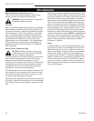
Appliance Model Kit Name
33RDV AT1CBB
33TDV AT1CBB
36RDV/TDV BT2CBB
39RDV/TDV CT2CBB