


32
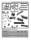
RDVN Series Direct Vent Gas Fireplace
20007628
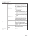
Kit Number
Conversion Parts Included with Kit 33DVCKP 36DVCKP 39DVCKP
Main Burner Orifice - LP 76776 20007908 20007907
Label, Conversion 10002876 10002876 10002876
Pilot, Orifice - LP 76263 76263 76263
Conversion Pressure Regulator Assembly - LP 74655 74655 74655
Label, SIT Valve -- -- --
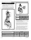
Convert Valve to LP
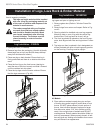
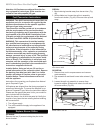
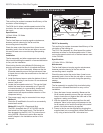
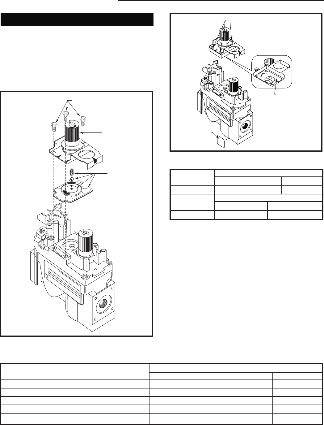
1. Using a Torx T20 bit or slotted screwdriver, remove
and discard the three (3) pressure regulator mount-
ing screws (A), pressure regulator tower (B) and
diaphragm (C). (Fig. 55)
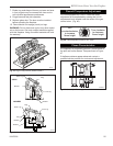
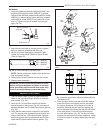
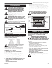
2. Insure the rubber gasket (D) is properly positioned
and install the new HI/LO pressure regulator assem-
bly to the valve using the new screws (E) supplied
with the kit. Tighten screws securely. (Fig. 56)
FC107
SIT820
valve conversion
10/03
A
B
C
O
F
F
P
I
L
O
T
O
N
FC107
Fig. 55 Remove mounting screws, pressure regulator tower
and diaphragm assembly, and discard.
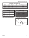
D
E
F
FC108
SIT
regulator
conversion
10/03
O
F
F
P
I
L
O
T
O
N
FC108
Fig. 56 Replace regulator.
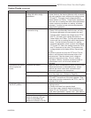
Gas Supply Pressure (inches w.c.)
Minimum Normal Maximum
LP (Propane) 10.8 11.0 14.0
Manifold Pressure (inches w.c.)
Nornal (HI) Normal (Low)
LP (Propane) 10.0” 6.3”
Pressure ranges are:
3. Install the enclosed installation label (F) to the valve
body where it can be seen.
4. Apply gas to system and relight appliance according
to manufacturer’s instructions.
5. With the main burner “ON”, test the new pressure
regulator assembly for leaks using a soap solution.
6. Relight the main burner in both the HI and LO posi
-
tions, and verify proper burner ignition and opera-
tion.
7. Check inlet and manifold pressures. Loosen screw
in test port 1/2 turn to measure pressure. Tighten
screw when measurement is complete.
Manifold pressure can be measured by using a 5/16”
I.D. hose in the right hand side of the valve and con-
necting a manometer. Two test gauge ports are acces-
sible for test gauge connection. Refer to Page 32.