


17
RDVN Series Direct Vent Gas Fireplace
20007628
ZCS101
Zero Clearance Sleeve
3/11/99 djt
Max. Length
12” (305mm)
#8 Screws (2)
#8 Screws
(2)
Adjustable
Zero Clearance
Sleeve
#8 Screws
(2)
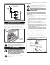
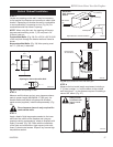
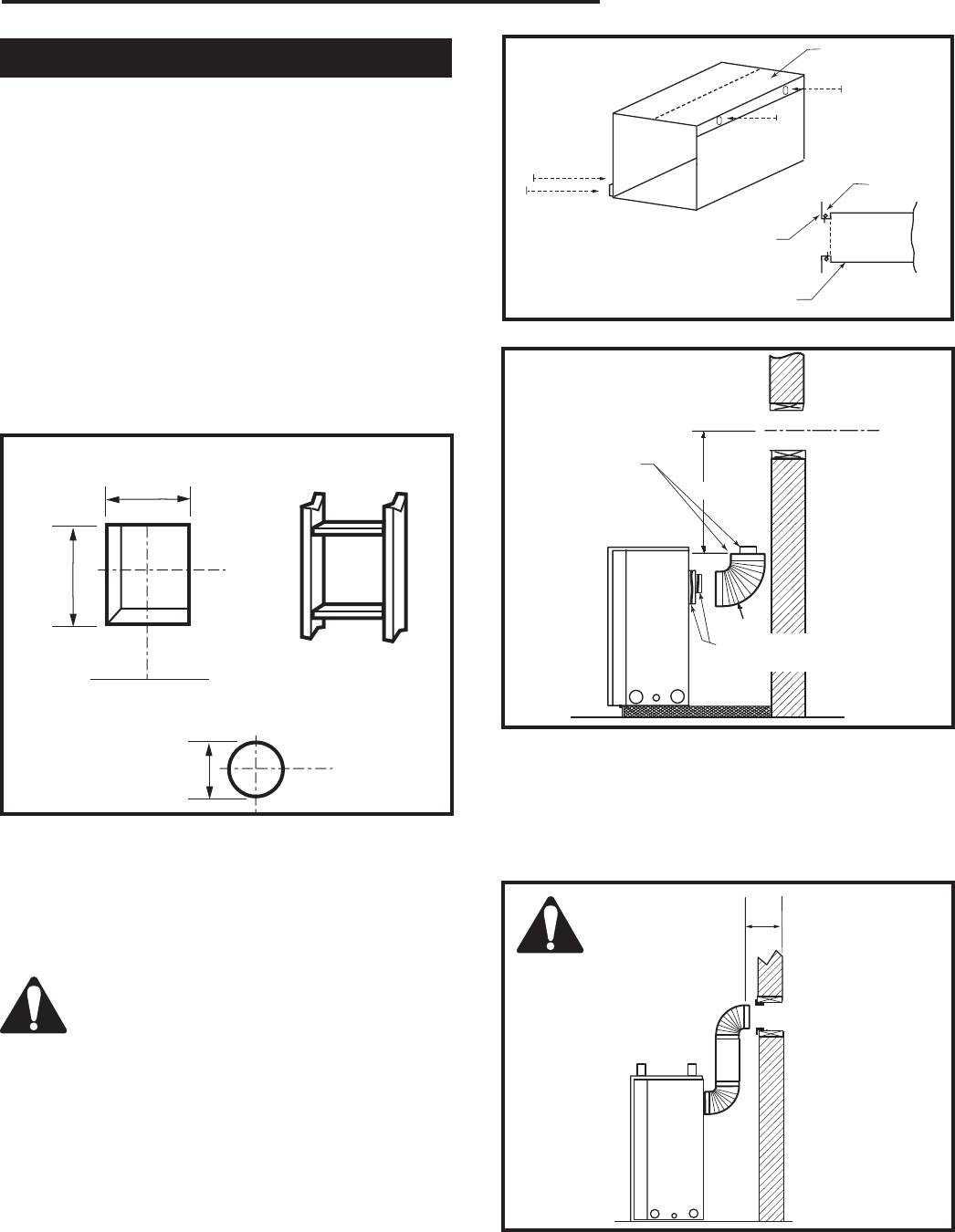
Adjustable Zero Clearance Sleeve
ZCS101
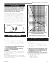
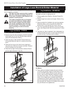
Fig. 25 Adjustable zero clearance sleeve.
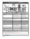
Firestop
VO584-100
Vent Opening
2/99 djt
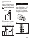
Vent Opening for Combustible Wall
9³⁄₈”
(240mm)
9³⁄₈”
(240mm)
Fireplace Hearth
Framing
Detail
Opening for Noncombustible Wall
7¹⁄₂”
(190mm)
VO584-100
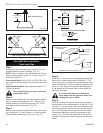
Fig. 24 Locate vent opening on wall.
STEP 1
Locate vent opening on the wall. It may be necessary
to first position the fireplace and measure to obtain hole
location. Depending on whether the wall is combustible
or noncombustible, cut opening to size. (Fig. 24) For
combustible walls first frame in opening.
NOTE: When using flex vent, the opening will have to
be measured according to the 1” (25 mm) rise in 24”
(610mm) vent run.
Combustible Walls:
(Fig. 24) Cut a 9³⁄₈”H x 9³⁄₈”W (240
x 240 mm) hole through the exterior wall and frame as
shown.
Noncombustible Walls:
(Fig. 24) Hole opening must
be 7¹⁄₂” (190 mm) in diameter.
Vertical Sidewall Installation
STEP 2
Measure wall thickness and cut zero clearance sleeve
parts to proper length (MAXIMUM 12”/305 mm). As-
semble sleeve and attach to firestop with #8 sheet
metal screws (supplied). Install firestop assembly. (Fig.
25)
Zero clearance sleeve is only required for
combustible walls.
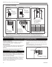
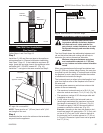
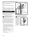
STEP 3
Apply a bead of high temperature sealant to the inner
and outer flue collars of the fireplace and using ap-
propriate venting component(s), attach to fireplace with
three (3) screws. (Fig. 26) Follow with the installation
of the inner and outer elbow. Again secure joints with
three (3) sheet metal screws. Wipe off any excess high
temperature sealant.
X
7TDVRT90
CFM143
2/2/01 sta
Ensure Pipes
are Concentric
Bead of Sealant
(If necessary)
CFM143
Fig. 26 Apply sealant to inner and outer pipe.
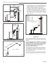
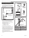
STEP 4
Measure the horizontal length requirement including a
2” (51mm) overlap, i.e. from the elbow to the outside
wall finish plus 2”, or the distance required if installing a
second 90° elbow. (Fig. 27)
CFM136
Rear Vent horizontal length
2/26/01 sta
X
CFM136
Fig. 27 Measure horizontal length including 2” overlap.
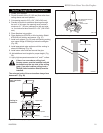
Always install
horizontal vent-
ing on a level
plane.