


Page 6
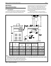
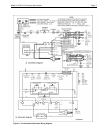
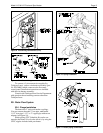
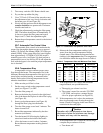
use 120 Volt, 60 Hz AC requires rewiring of the
heater. This should be done by a certified electrician
only, as with all wiring. To wire the heater for 120
Volt, 60 Hz AC, follow the alternate 120V wiring
method depicted in Figure 6. Additionally, the ignition
control module must be rewired. The wire from the
terminal marked IGN/240 must be removed from that
terminal and placed on the terminal marked IGN/120.
Electrical wiring must be in accordance with the
latest edition of the National Electric Code (NEC),
ANSI/National Fire Protection Association (NFPA)
70, unless local code requirements indicate otherwise.
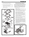
To wire the Laars Lite heater:
1. Wire the heater to a 120V or 240V /60 Hertz
(Hz) electrical source.
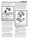
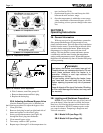
2. Connect the wires from the source to the leads on
the right side of the heater in the space behind the
ignition control (see Figure 8).
3. Remove the screw located to the lower right of
the transformer and open the hinged cover.
NOTE: No external junction box is required.
2F-2. Auxiliary Time Clock Wiring
(LLD or LLG)
If you install a time clock to control the filter
pump operation, it is recommended that the time clock
have its own low voltage (Fireman’s) switch to turn off
the heater before turning off the pump. The switch
should shut off the heater about 15 minutes before the
filter pump shuts off. This will allow for a more
efficient operation by removing any residual heat
contained in the heat exchanger back to the pool.
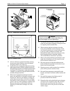
To install a time clock auxiliary switch into the
heater wires (see Figure 9):
1. Remove heater door.
2. Remove the factory installed wire between
terminals 1 and 2 on the terminal strip (see Figure
9).
3. Connect the wires from the time clock auxiliary
switch to the two terminals. Use American Wire
Gage (AWG) No. 14 gauge stranded copper wire
with a temperature rating of 221°F (105°C) or
greater.
The length of the wire between the heater and the
time clock should not exceed 10-15 feet (4.57 m). The
contact points of the time clock switch should be silver,
or a low resistance alloy.
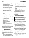
2F-3. Remote Operation
(Model LLD Only)
The Laars Lite pool/spa heater controls can
Caution
Permanent damage to the gas valve will occur
if the following procedures are not followed.
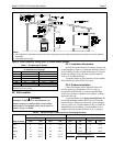
8. If the gas supply pressure is less than required,
check for under-sized pipe between the meter and
the heater, a restrictive fitting, or an undersized
gas meter. Gas supply pressures to the heater are
listed in Table 4.
NOTE: The maximum inlet gas pressure must
not exceed the specified value. The minimum value
listed is for the purpose of input adjustment. Refer to
Table 4.
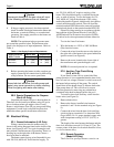
Table 4. Gas Supply Pressure Requirements
Supply Pressure Natural Gas Propane Gas
Water Column in. (mm) in. (mm)
Minimum 6 (152) 10 (254)
Maximum 14 (356) 14 (356)
9. Before operating the heater, test the complete gas
supply system and all connections for leaks using
a soap solution. Do not use an open flame.
Caution
Some leak test solutions (including soap and
water) may cause corrosion or stress cracking.
Rinse the piping with water after testing.
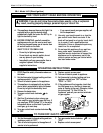
2E-2. Special Precautions for Propane
Gas (LLG Only)
Liquefied petroleum (LP) gas is heavier than air.
Therefore, do not install pool heaters using LP gas in
pits or locations where gas might collect. Locate
heaters a safe distance from LP gas storage and filling
equipment. Consult local codes and fire protection
authorities about specific installation restrictions.
2F. Electrical Wiring
2F-1. General Information (LLD Only)
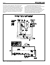
Wiring connections must be made exactly as
shown in the wiring diagram found on the inside of the
heater (see Figures 6 and 7 for typical examples) and
must include a definite means of grounding. There is a
bonding lug on the right side of the heater, where a
bond wire must be attached.
The heater comes factory-wired intended for use
with 240 Volt, 60 Hz AC field electrical supply. To