Model LLG & LLD Pool and Spa Heater
Page 11
Caution
It may be necessary to have help lifting the
heat exchanger out and replacing it.
15. Lift out the heat exchanger assembly and set it
aside. Re-install heat exchanger 180 degrees from
it's original position (header left).
16. When replacing the heat exchanger from the
heater, the end baffles must be replaced. Each
one is held in place by two screws which mount
to the top of the combustion chamber wall.
Reinstall the baffles on the front and rear of the
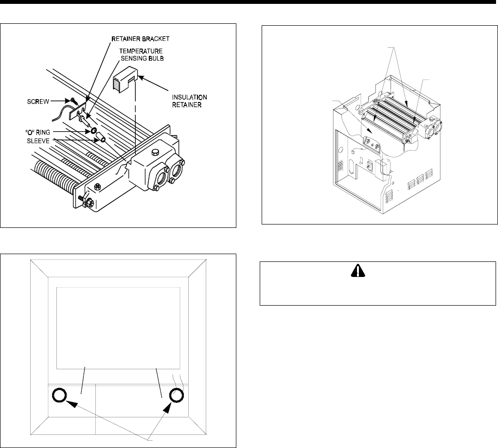
heat exchanger before continuing with the
"Reversible Water Connections" procedure.
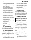
17. Remove the plastic bushing from the hole on the
right side of vestibule cover. Re-install it in the
hole on the left vestibule cover.
18. Re-route pressure switch tube and thermostat
bulb assembly through hole in left side of (vesti-
bule) cover in reverse order.
19. Remove pressure switch retainer from vestibule
panel (allow pressure switch to float).
20. Re-install the temperature sensing bulb in the
header, and fasten it with the retainer bracket and
screw.
21. Re-install the compression fitting at end of
pressure switch line into header.
22. Route the white wiring beside the heat exchanger
and down to the original location. Be careful to
keep the wires away from the flue collector.
Secure white wires to the pressure switch tube
with tie straps.
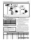
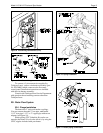
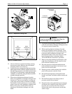
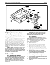
Figure 14. Temperature sensing bulb.
12. Unscrew the brass compression fitting securing
the pressure switch. Remove tube from header
and gently bend it out of the way.
13. Loosen the screw securing the temperature sensing
bulb retainer bracket. Slide the retainer bracket off
the bulb flange and remove the bulb from the header
(see Figure 14). Pull pressure switch tube through
vestibule cover hole first, then pull thermostat bulb
assembly through same hole.
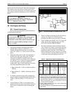
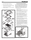
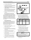
14. When removing the heat exchanger from the
heater, the end baffles of the heat exchanger must
be removed. There are two baffles covering part
of the front and rear tubes of the heat exchanger.
Each baffle is held in place by two screws which
mount to the top of the combustion chamber wall.
Remove the screws and the baffles before at-
tempting to lift the heat exchanger out of the
heater.
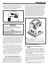
Figure 15. Vestibule covers.
FRONT
PLASTIC BUSHING
LEFT
VESTIBULE
COVER
RIGHT
VESTIBULE
COVER
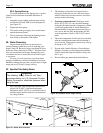
Figure 16. Heat exchanger and end baffles.
Heat Exchanger
End Baffles
Combustion
Chamber Wall
Heat Exchanger


