


Model LLG & LLD Pool and Spa Heater
Page 13
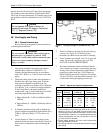
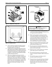
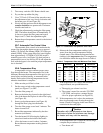
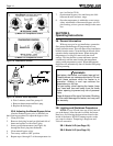
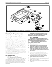
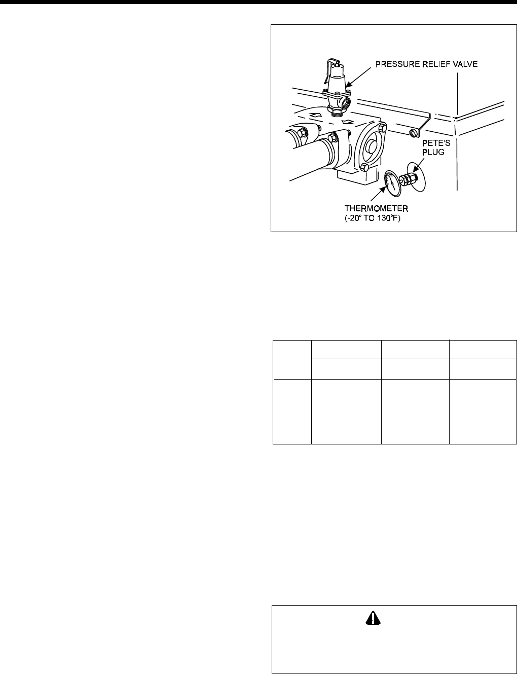
Figure 17. Thermometer and pressure relief valve.
3. Turn rotary switch to ON. Heater should start.
4. Pry out the top rubber dirt plug.
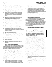
5. Use a 7/32 inch (5.55 mm) Allen wrench to turn
the adjustment screw very slowly clockwise until
the heater goes off (see Figure 18).
6. Slowly turn the pressure switch adjustment screw
counter-clockwise one-quarter turn. The heater
should come back on.
7. Check the adjustment by turning the filter pump
OFF. The heater should shut off immediately. If
it does not, restart the filter pump and repeat
Steps 6 and 7. Check the adjustment again.
8. Return the pool temperature control to the desired
temperature.
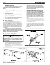
2G-7. Automatic Flow Control Valve
The automatic flow control valve maintains the
proper flow through the heater at rates up to approxi-
mately 125 Gallons Per Minute (GPM) (474 liters per
minute [LPM]). If the system filter-flow rate is higher
than approximately 125 GPM (474 LPM), install a
manual bypass valve (see Figure 18), then perform a
temperature rise test (see Section 2G-8) and adjust the
flow with the bypass valve until the proper temperature
rise is obtained.
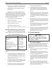
2G-8. Temperature Rise
A temperature rise test confirms proper water
flow through the heater. The temperature rise is the
difference between the temperature of the pool or spa
water before and after heating, as measured in the
header. Perform the following temperature rise test
when the installation is complete:
1. Make sure the pool filter is clean.
2. Set the rotary switch on the temperature control
panel (see Figure 17) to OFF.
3. Turn the filter pump off.
4. Remove the drain plug located on the right-hand
side of the heater and replace it with a Pete's plug
(see Figure 16).
5. Insert a pocket thermometer (see Figure 16)
through the Pete's plug into the header.
6. Turn the filter pump on and wait 3 minutes. The
heater is turned off.
7. Record the temperature indicated by the ther-
mometer (cold water).
8. Turn the heater ON following the lighting in-
structions found on the inside of the heater.
9. Allow the heater to run for about 3 minutes.
Record the new temperature reading (heated
water).
10. Subtract the first temperature reading (cold
water) from the second temperature reading
(heated water). The difference between the two
readings is the temperature rise. The temperature
rise should be within the range shown in Table 6.
11. If the temperature rise is below the minimum
range indicated, two possibilities arise:
a. The supply gas volume is too low.
b. The system's water flow exceeds 125 GPM
(474 LPM), and requires a manual bypass
valve for proper operation (see Figure 19).
12. If the temperature rise is above the maximum,
there is not enough water flowing through the
heater. Check for clogging in the water filter or
restriction in the water pipes.
Caution
Operation with the temperature rise above
maximum or below the minimum can damage
the heater and may void the warranty.
13. If the temperature rise is within the correct range,
complete the procedure as follows:
a. Turn heater off.
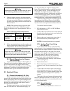
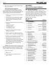
Minimum Minimum Maximum
Size GPM (LPM) °F (°C) °F (°C)
125 20 (76) 27 (15) 36 (20)
175 20 (76) 33 (19) 42 (24)
250 25 (95) 33 (19) 42 (24)
325 30 (114) 28 (16) 38 (21)
400 30 (114) 30 (17) 39 (22)
Table 6. Temperature Rise and Minimum Flow Rates