


Page 20
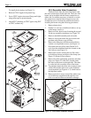
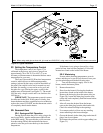
4B. Parts List
Description Part Number
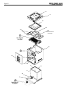
A. VENTING ASSEMBLY
1. Top Enclosure Weldment ................................... R0313201-05
2. Top Filler Plate .................................................... 10535201-05
3. Flue Collector ..................................................... R0316401-05
(R0316406-10 for Canada)
4. Rainshield Kit ..................................................... R0318301-05
(R0318311-15 for Canada)
**5. Redundant Limit (LLG) ............................................ R0313900
6. Drafthood Kit ....................................................... 10561401-05
(10561411-15 for Canada)
7. Vent Cap Kit ........................................................ 10561501-05
(10561511-15 for Canada)
B. JACKET COMPONENTS
1. Jacket Assy ........................................................ R0316501-05
2. Gap Closures .......................................................... R0318400
3. Door w/Latch ...................................................... R0313401-05
4. Fusible Link Assy .................................................... R0012200
5. Pressure Switch, 2 psi ............................................. R0013200
5. Pressure Switch, 1 psi ............................................. R0011300
5. Pressure Switch, 1-10 psi ....................................... R0015500
6. Tube, Siphon Loop ................................................... 10545200
7. Grommet Kit ............................................................ R0316300
*8. Ignition Control Assembly (LLD) .............................. R0317500
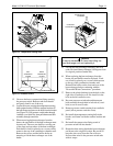
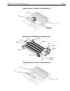
C. COMBUSTION PANEL ASSEMBLY
1. Chamber panel side, left/right .................................. R0316600
2. Chamber panel back ........................................... R0316701-05
*3. Chamber panel front (LLD) ................................. R0316801-05
**3. Chamber panel front (LLG) ................................. R0317801-05
*4. Ignitor (LLD) ............................................................ R0317200
*5. Ignitor Assembly (LLD) ............................................ R0317400
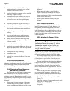
D. HEAT EXCHANGER ASSEMBLY
Complete Heat Exchanger Assy ................................. 10606401-05
1. Cast Iron Return Header .......................................... R0058300
2. Cast Iron Inlet/Outlet Header ................................... R0056400
3. Bronze Return Header ............................................. R0054600
4. Bronze Inlet/Outlet Header ...................................... R0016800
5. Heat Exchanger, Tube Assy ............................... R0018101-05
6. Header Gasket Kit ................................................... R0050800
7. Flange Assy ............................................................ R0055000
8. Cast Iron Flow Valve Assy ................................... 10701301-05
8. Bronze Flow Valve Assy ...................................... 10701401-05
9. Bracket Heat Exchanger ........................................... 10457000
10. Baffle, Heat Exchanger, 8 .................................... 10697401-05
11. Clamp, Holddown ..................................................... 10726200
12. Bracket, Holddown ................................................... 10726300
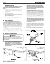
5. Be sure all combustion air and ventilation open-
ings are not blocked.
3H-2. Professional Inspection
In addition, annual inspections by a qualified
professional technician are recommended to keep the
heater operating safely and efficiently through the years.
The following basic checks should be performed.
1. Check for loose or broken wires and terminal
connections.
2. Verify pressure switch operation by cycling
the spa pump on and off a few times. The
heater should go off immediately after the
pump stops.
3. Inspect the electrical controls, specifically the
following:
a. High limit controls.
b. Pressure switch.
c. Temperature control.
d. Automatic gas valve.
4. Inspect the venting system for blockage,
leakage, and corrosion.
5. Check for spider webs in the pilot and main
burner orifices — especially at Spring startup.
6. Conduct a normal operating cycle and observe
that the sequence proceeds as intended.
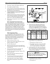
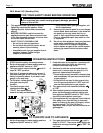
7. Inspect the external surfaces of the heat
exchanger tubes for black carbon soot buildup
by placing a mirror between and under the
burners when the heater is firing. Remove any
soot that has collected on the tubes, and
correct the cause.
NOTE: After installation and first startup, check
the heat exchanger for black carbon soot buildup after
the following periods of operation: 24 hours, 7 days,
30 days, 90 days, and once every 6 months thereafter.
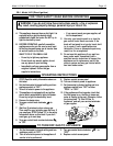
Proper flames appear:
a. Blue in color.
b. 1 to 4 inches (25 to 102mm) high above
burner surface.
SECTION 4.
Parts List for Laars Lite Heater
4A. General Information
To purchase parts or obtain a comprehensive
maintenance manual for the Laars Lite heater, contact
your nearest Teledyne Laars dealer or distributor. If
they cannot supply you with what you need, contact
the Customer Service Manager, Teledyne Laars, 6000
Condor Drive, Moorpark, California, 93021,
Telephone (805) 529-2000.