


Page 12
injector to prevent ozone and air from entering
the heater.
• When chemical feeders are used, plumb the
feeder downstream of the heater and install an
inline check valve between the heater and the
feeder (a minimum of 18" is required between the
heater and the check valve).
• Never deposit chemicals directly in the pool
skimmer.
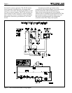
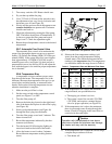
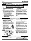
2G-5. Pressure Relief Valve
A pressure relief valve is not furnished with the
Laars Lite heater, except in Canada, however, it is
recommended and may be required by local codes.
To install a pressure relief valve, remove the 3/4
inch (19 mm) brass plug on the in/out header with the
valve (see Figure 16). The setting of the valve should
be at or below the lowest working pressure of filter
system components.
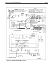
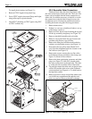
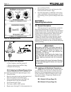
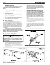
2G-6. Adjusting the Pressure Switch
Caution
The pressure switch should be adjusted to turn
the heater off when the pump is off. Setting
the switch to close at too low of a flow can
damage the appliance. Adjust the switch to
turn the heater off, not on.
The pressure switch is preset at the factory for
activation at 2 psi (14 kPa). Adjust the pressure switch
only if any part of the filter system piping is 3 feet
(0.91 m) or more above the top of the heater jacket.
Do not adjust the pressure switch if the heater is
installed more than 15 feet (4.57 m) below or 6 feet
(1.83 m) above the pool surface. Consult your local
Teledyne Laars representative for recommendations.
On some installations, the piping from the heater
to the pool is very short. The back pressure could be
too low to trigger the pressure switch. If this happens,
it may be necessary to install a directional fitting or
elbows where the return line enters the pool. This will
increase back pressure enough for the heater to operate
properly.
Make sure the pool filter is clean before making
any pressure switch adjustment: A dirty filter will
restrict the water flow and the pressure switch cannot
be adjusted properly. To adjust the pressure switch:
1. Turn the control panel rotary switch to OFF (see
Figure 17).
2. Turn filter pump on. If a two-speed pump is used,
make sure it is at high speed.
(NOTE: Heater should not be allowed to fire on
low speed).
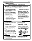
23. Connect the white wire labeled PS to the pressure
switch and the other white wire to its original
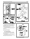
location on the Fireman's switch.
24. Replace jacket/plugs grommets, and re-install the
drain plugs. Tighten securely.
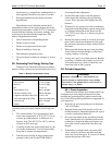
25. Install the flue collector assembly. Be sure the
bottom lips are inside the grooves on the front
and rear tile covers and are not pinching any
wires.
26. Reconnect yellow wires (Model LLG only) to
redundant limit fuse on the flue collector.
27. Attach the flue collector holddown clamps to the
clips located under the two center header bolts.
28. Replace the gap closures and tighten the screws
securely.
29. Re-cover the header sensors with fiberglass
insulation, and replace the insulation retainer.
30. Double-check to make sure the wiring is not
pinched against sharp edges, or resting on the flue
collector assembly.
31. Re-install rainshield assembly.
32. Replace the top assembly. Make sure the tabs are
outside the heater jacket. Fasten the top assembly
with the hex-head screws.
33. Install plastic tie wraps on wiring.
34. Install heater door.
35. Reinstall the vent cap or drafthood, if one was
removed.
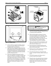
2G-3. Check Valve Installation
Install a check valve if there is any chance of back-
siphoning when the pump stops. Do not install any other
valve in the piping between the heater outlet and the
pool, unless it is being used as a diverter valve.
2G-4. Chlorinators, Ozone Generators,
and Sanitizing Chemicals
The Teledyne Laars Lite heater is manufactured
with materials that are not compatible with high
concentrations of ozone, chlorine, bromine, or other
sanitizing chemicals. Heater damage caused by exces-
sive chemicals or improper ozonation is not covered by
the Teledyne Laars warranty. Be sure to adhere to the
following:
• When ozone is injected upstream of the heater,
install an offgas mixing chamber, or an ozone
bypass system between the heater and the ozone