


Teledyne API Model 300M CO Analyzer Instruction Manual, 04033, Rev. A
2. Confirm that the following voltages are present on the V/F Board:
A. +5V between V/F TP 4 and V/F TP 5
B. +15V between V/F TP 1 and V/F TP 3
C. -15V between V/F TP 2 and V/F TP 3
D. +12V between Mother Board Pad J13,6 and J13,7
If any of these voltages is incorrect, it is probable that the DC Power Supply Board is faulty and
should be replaced.
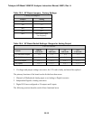
Four Temperature linearization circuits are contained on the DC Power Supply board. The
outputs of these circuits can be checked measuring the voltages at test points on the board as
follows:
TP1 Sample Temp
30
°
C=2.5 V,
±
0.125 V/
°
C
TP2 Optical Bench
50
°
C=2.5 V,
±
0.125 V/
°
C
TP3 Filter Wheel Temp
50
°
C=2.5 V,
±
0.125 V/
°
C
TP4 Chassis Temp
20
°
C=2.5 V,
±
0.125 V/
°
C
If any of these voltages is incorrect, check thermistor operation as described in Section 10.6.2. If
thermistors are operating correctly, it is probable the DC Power Supply Board is defective and
should be replaced.
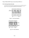
10.6.5 Checking the Synchronous Demodulator Board
A schematic and physical diagrams of the Synchronous Demodulator Board are shown in
drawings 798 and 799 in Appendix C.
Proper operation of the Synchronous Demodulator can best be confirmed by performing the
Electric Test under Diagnostic menu.
When activated, the Electric Test Diagnostic should produce a constant, stable analyzer output of
approximately 400 PPM. If this stable output is produced it is probably that the Synchronous
Demodulator is functioning properly.
If Electric Test does not produce a stable output, check the following:
1. Confirm proper operation of the V/F Board as described in Section 10.6.3.
2. Confirm that during Electric Test the values of the CO MEAS and CO REF test functions are
between 2500 mV and 4500 mV.
10-15