Teledyne API Model 300M CO Analyzer Instruction Manual, 04033, Rev. A
There are two acceptable methods of generating accurate CO concentrations for calibrating the
Model 300M.
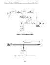
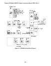
One method uses a single cylinder of CO -in-air and a means of accurately diluting the cylinder
gas with zero air. This is illustrated in Figure 8-1. Alternatively, several cylinders of CO -in-air,
of appropriate concentrations, may be used without dilution. The cylinder concentrations must be
traceable to NIST standards. Flow correction for standard temperature and pressure (STP) is not
required with either method. With dilution, the correction is self-canceling. With the multi-
cylinder method, the correction is not applicable.
8.2.1 Procedure
1. Set the analyzer to the desired range.
2. Set the calibration system to deliver a flow of at least 1000 cc/min. The Model 300M draws
approximately 800 cc/min. (See Section 8.1 and Figure 8-2 for vent flow calculation.)
3. Pre-calculate the calibrator flow to be sure that a CO concentration of 80% of URL (upper
range limit) can be produced with enough surplus flow to provide an adequate vent flow.
4. Connect the analyzer REC (recorder) terminals to a calibrated strip-chart recorder. For best
accuracy, connect a DVM to the same terminals or to the DAS (Data Acquisition System)
terminals.
The standard output voltage of 0-5.0 VDC.
If, in service, data is to be collected from a device (printer) connected to the RS-232 port, then
the calibration data must be collected from the RS-232 port.
5. Set the calibrator to deliver zero air to the manifold.
6. Push “CAL” on the analyzer front panel.
7. Enter password. (If Enabled)
8. Wait 10 minutes for the analyzer to stabilize.
9. Push “ZERO” and “ENTR” on the front panel. The analyzer is now “zeroed.”
10. Push “EXIT”. (Return to sample mode.)
11. Record the DVM reading and the percentage chart reading or the RS-232 output.
12. Set the calibrator to produce 75% to 85% of the URL (upper range limit). This will be 400
PPM
±
25 PPM on the 500 PPM range.
8-4


