


NOTE: DIAGRAMS & ILLUSTRATION ARE NOT TO SCALE.
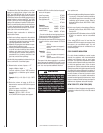
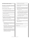
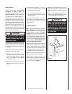
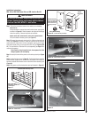
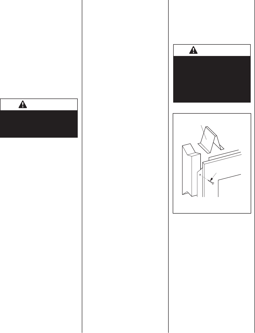
Figure 7
8d Nail
Top Spacer
9
The fi rebox may be positioned and then the
framing built around it, or the framing may
be constructed and the fi rebox positioned into
the opening.
Usually, no special fl oor support is needed for
the fi rebox, however, to be certain:
1. Estimate the total weight of the fi rebox
system and surround materials such as
marble, brick, stone, etc., to be installed
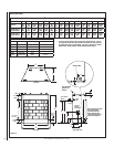
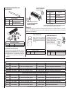
(see Product Referance Table on Page 10
for appliance weight).
2. Measure the square footage of the fl oor
space to be occupied by the system and
surrounds.
3. Note the fl oor construction, i.e. 2" x 6", 2" x
8" or 2" x 10", single or double joists, type
and thickness of fl oor boards.
4. Use this information and consult your lo-
cal building code to determine if you need
additional support.
If you plan to raise the fi rebox, build the plat-
form assembly then position fi rebox on top.
Secure the platform to the fl oor to prevent
possible shifting.
Firebox Installation
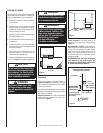
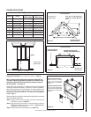
Step 1. Frame these appliances as illustrated in
Figures 9 through 11. All framing details must
allow for a minimum clearance to combustible
framing members as shown in Figures 2
through 6. Also refer to appliance specifi cations
on Page 10 . Headers may be in direct contact
with the appliance top spacers but must not
be supported by them or notched to fi t around
them. All construction above the appliance must
be self supporting, DO NOT USE THE APPLI-
ANCE FOR STRUCTURAL SUPPORT.
Note: The framed depth from a framed wall,
must always be measured from a fi nished
surface. If a wall covering such as drywall is
to be attached to the rear wall, then the depth
must be measured from the drywall surface. It
is important that this dimension be exact.
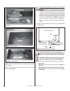
Step 2. Level the fi rebox by checking the top
edge of the fi rebox. Shim if necessary.
Step 3. Fireplace should be secured to side
framing members using the full length nailing
tabs at the top and bottom of the fi replace front
face. Use 8d nails (see Figure 7).
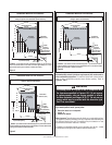
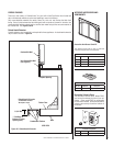
Firebox Framing
Construct fi rebox framing following Figures
9 through 11 and Table 1 on Page 11 for
your specifi c installation requirements. Refer to
Figure 8 on Page 10 for fi rebox dimensions.
The fi rebox may be installed directly on a
combustible fl oor or raised on a platform of
an appropriate height. Do not place fi rebox on
carpeting, vinyl or other soft fl oor coverings. It
may, however, be placed on fl at wood, plywood,
particle board, metal or other hard surfaces
which extend the full width and depth of the
enclosure. Be sure fi rebox rests on a solid
continuous fl oor or platform with appropriate
framing for support and so that no cold air can
enter room from under the fi rebox.
Note: The nailing fl ange and the area directly
behind the nailing fl ange is exempt from the
clearances described on the fi rebox clearance
label.
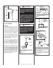
Step 4. To safely operate the heater with con-
sideration of the mantel clearances the canopy
must be installed (Model UVF-36 Only).
CAUTION
Do not block the heat-circulating
air inlets and outlets on these
fi reboxes. Doing so may create a
potential fi re hazard.
IMPORTANT
Under no circumstances shall the
fi rebox top spacers be removed
or modifi ed (see Figure 8). The
header may be in direct contact
with the top spacers but must not
be supported by them or notched to
fi t around them.