


NOTE: DIAGRAMS & ILLUSTRATION ARE NOT TO SCALE.
12
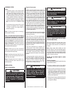
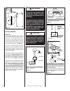
OPTIONAL EQUIPMENT
Blower Kits
The FBK-100 Blower Kits are used when
a wall-mounted ON/OFF blower switch is
desired, and the FBK-200 Blower Kits are
used when a wall-mounted variable speed
blower control (rheostat) is desired. A Junction
Box / Electrical Kit is also required to install these
kits (purchased separately - see Page 15).
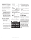
The blower is installed beneath the fi rebox.
Room air is drawn in through the side slots
of the fi replace, heated as it passes across the
fi rebox, and discharged through the upper area
of the fi rebox opening.
The installation instructions for installing these
blower kits are on Pages 12 through 14. Also see
the installation instructions provided with the
blower kits (Form #750,028M). For electrical
requirements, refer to Figures 14, 15 & 16.
If the blower kit is to be installed at the time of
installation or at a later date, the main power
supply must be installed at the time of instal-
lation. This will require that the electrical
connections must be made BEFORE the fi rebox
is framed and enclosed in the fi nished walls.
Route a 3-wire, 120 VAC, 60 Hz, 1 ph power
supply and connect to electrical receptacle wires
and wall switch or rheostat.
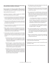
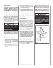
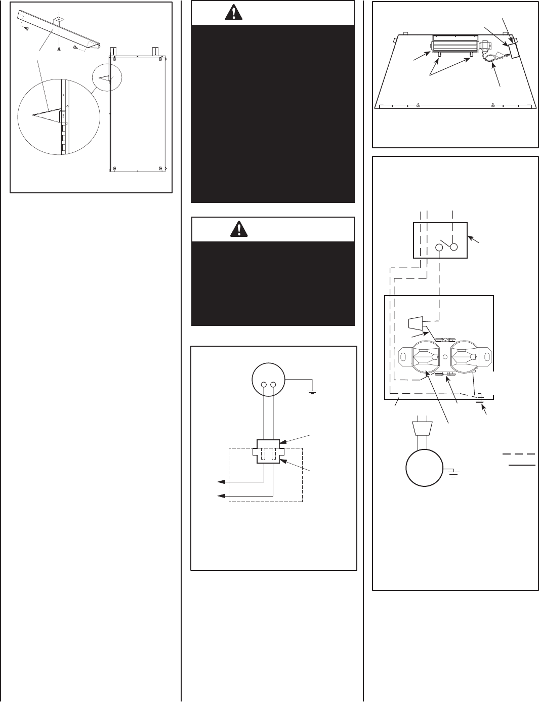
Grounded
to Appliance
Blower Motor
Motor Plug
Receptacle
120V
Appliance Junction Box
120V, 60HZ,
1PH BLOWER
CONTROL CIRCUIT
WIRING
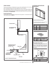
Junction
Box
Factory Wired
Blower
Tab
Intact
Plug blower
into this
receptacle
Ground - Green
* Wall-mounted ON/
OFF Blower Switch
or Variable Speed
Control Switch.
Ground
HOT SIDE OF
RECEPTACLE
*An ON/OFF Wall Switch is used with the FBK-100 kit
(fi eld provided or sold separately - order P/N 85L87); A
Variable Speed Control (provided) is used with the FBK-
200 kit. The installation of these kits also require a
Junction Box / Electrical Kit, not included. See Page
15 for ordering information.
Note: If any of the original wire as supplied must be
replaced, it must be replaced with type AWM 105
degree C - 14 gage wire.
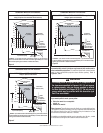
Neutral - White
120 VAC Black
Green
Ground
Screw
NEUTRAL
SIDE OF
RECEPTACLE
Black
Field Wired
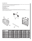
Figure 16
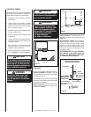
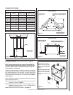
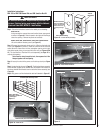
Blower
* Junction Box
Bend blower mounting
tabs up to secure
blower in place
* Electrical Outlet
Tie a loose knot in power
cord to take up slack
Top View
Figure 15
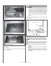
Figure 14
Note: If any of the original wire as supplied must be
replaced, it must be replaced with type AWM 105
degree C - 14 gage wire.
* The Junction Box / Electrical Kit is not included.
See Page 15 for ordering information.
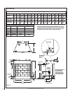
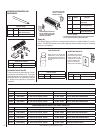
Figure 13
Canopy
Side View
IMPORTANT
The Ground Lead must be connected
to the green screw (located on the
junction box). Failure to do this
could result in an electrical short or
shock injury.
The appliance must be electrically
grounded in accordance with local
codes or, in the absence of local
codes, the national electrical code,
ANSI/NFPA 70-(latest edition). (In
Canada, the current CSA C22-1
Canadian Electrical Code).
CAUTION
Electrical connections should
only be performed by a qualifi ed,
licensed electrician. Main power
must be off when connecting to
main electrical power supply or
performing service.