


NOTE: DIAGRAMS & ILLUSTRATION ARE NOT TO SCALE.
14
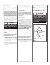
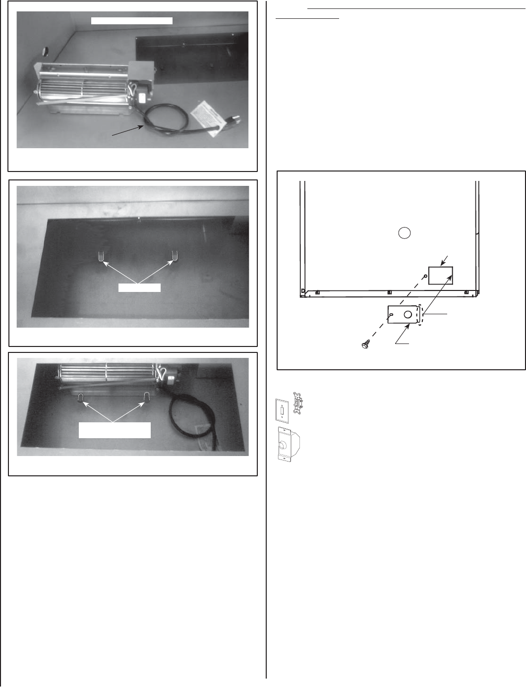
Step 8. Ensure that power supply wires are NOT "live" before making
these connections). Install J-Box Cover Plate as follows:
Feed the * Romex wires (or other equivalent plastic insulated wire
- Refer ANSI/NFPA 70 - National Electrical Code - Latest Edition)
through the J-Box Cover retangular opening, then connect to the
J-box wires. The strain relief bushing should be pressed into the
knock-out on J-box cover around the Romex (this will provide
protection to the wires and prevents strain against connections
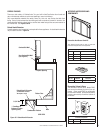
from J-box). See Wiring Diagram - Figure 16. Install the cover
plate over J-Box opening on appliance as shown in Figure 25.
Note: Wire connections should be positioned inside of the ap-
pliance.
* Romex is a plastic insulated wire from power supply - sometimes called
non-metallic sheath.
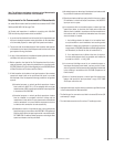
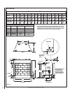
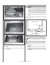
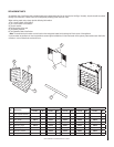
Cabinet Base
Figure 22
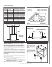
Figure 23 -
UVFRC-4228 Shown
Figure 24 - UVFRC-4228 Shown
Loose knot in power
cord to take up slack
Firebox
fl oor
Model UVFRC-4228 Shown
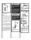
Model UVFRC-4228
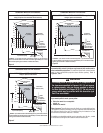
Locating Tabs
Bend Locating Tabs Over
(into notches)
Use screw provided and
secure in place as shown
The notched side of
cover plates goes inside
fi rebox panel
Screw
Cover Plate
Right Side Panel of Firebox
Figure 25 - Installing J-box Cover Plate - All Models
Step 9. Follow the instructions below for the kit you are installing:
FBK-100 Kits - Install a fi eld-provided (or P/N 85L87) ON/OFF wall
switch in a convenient location on a wall, near the fi replace.
FBK-200 Kits - Install the kit-provided variable speed control (rheo-
stat) in a convenient location on a wall, near the fi replace.
Step 10. Follow the instructions below for the model you are installing:
Model UVF-36:
Reinstall the blower access panel that was removed on Step 1 (see
Figure 18).
Models UVFRC-3628, UVFRC-3628-H, UVFRC-4228 & UVFRC-4228-H:
Reinstall the bottom refractory panel that was removed on Step 1
(see Figure 17).
J-Box opening
on appliance
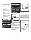
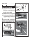
Step 6. Route a 3-wire, 120 VAC, 60 Hz, 1 ph power supply to the right
side of appliance.
Step 7. Locate the J-Box cover (provided in J-Box Kit). Remove the round
knock-out (see Figure 19).