


NOTE: DIAGRAMS & ILLUSTRATION ARE NOT TO SCALE.
A
B
11
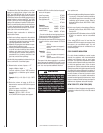
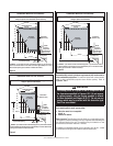
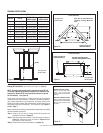
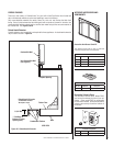
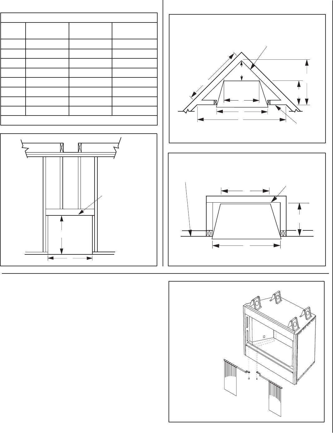
FRAMING SPECIFICATIONS
Figure 9
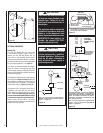
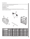
Canopy Kit Installation (see ordering information on Page 16)
NOTE: A canopy comes standard and is required for model UVF-36.
The factory-supplied canopy must be installed on the fi rebox for safe
operation for model UVF-36 in all installations (this part is optional
for other models). See
Figure 13.
These canopy kits are design to be fi tted to the face of the appliance
directly above the fi rebox opening. In addition to providing an aestheti-
cally pleasing appearance to your appliance, the canopy reduces heat
effects to decorative mantels and fi nish materials located directly above
the fi replace and reduces the Mantel / Trim clearances (see Figures 4,
5 & 6 on Page 7).
Please read this entire manual and understood thoroughly before proceeding
with the installation of these kits.
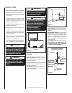
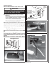
Step 1. Using a 5/16" nut driver or socket, remove the screen and rod
assemblies as shown in Figure 12.
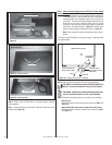
Step 2. Align the canopy with the holes in the side frames as shown in
Figure 13. Install three screws as shown in Figure 13. Make
sure canopy is level and secure.
Step 3. Reinstall screen and rod assemblies (see Figure 12).
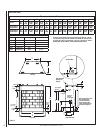
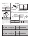
Framing Dimensions
Opening UVF-36
UVFRC-3628 &
UVFRC-3628-H
UVFRC-4228 &
UVFRC-4228-H
A 42-1/4" (1073) 42-1/4" (1073) 48-1/4" (1226)
B 40-1/4" (1022) 44-1/4" (1124) 44-1/4" (1124)
C 23-9/16" (599) 23-9/16" (599) 29-9/16" (751)
D 11-1/4" (286) 11-1/4" (286) 14-1/4" (362)
E 63-1/2" (1613) 63-1/2" (1613) 69-1/2" (1765)
F 31-3/4" (807) 31-3/4" (807) 34-3/4" (883)
G 20-1/2"( 521) 20-1/2"( 521) 20-1/2"( 521)
H 44-3/16" (1122) 44-3/16" (1122) 49-1/8" (1248)
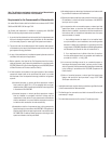
Table 1 -
This Table corresponds to Figures 9, 10 & 11
Rough Framing Face
(Unfi nished Shown)
Back Wall Of Chase/Enclosure
Including Finishing Materials If Any
Back Wall Of Chase/Enclosure
Including Finishing Materials
If Any
Rough Framing Face
(Unfi nished Shown)
Corner Installation
A
A
C
D
H
F
G
E
C
G
Parallel Installation
Figure 10
Figure 11
This Figure corre-
sponds to Table 1
This Figure corre-
sponds to Table 1
This Figure corre-
sponds to Table 1
Header
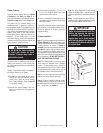
Figure 12
Removing Screens & Rods:
Remove screws (see dotted
lines). Pull out rods from
locating holes on side of fi rebox
opening.
Reinstalling Screens & Rods:
Insert rods into corresponding
locating holes on sides of fi rebox
opening, then reinstall screws
as shown.