


27
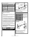
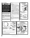
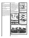
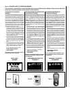
Step 5. WIRING - OPTIONAL FORCED AIR
BLOWER (FBK-100) (See Figure 45) -
An optional ON/Off (FRS) control switch is also
available (installs on bracket below valve). An
electrical outlet box is factory installed for the
connection of the electrical power supply to
the blower.
1. Route a 3-wire, 120Vac 60Hz 1ph power
line to the lower right rear corner of the
appliance.
2. Connect the black supply wire to the top
outlet's black pigtail lead and to the switch's
black lead. Connect the white supply wire to
the neutral terminal of the outlet box.
CAUTIONS
•
Remove the carton support from
the control compartment before
operating the appliance.
•
Ensure that wires are positioned
away from hot surfaces and sharp
edges.
•
Do not connect the optional wall
switch to a 120 Volt AC power
supply.
See Figure 45. It is not necessary to remove
the outlet box.
3. Connect the ground supply wire to the outlet
box green ground screw as shown.
4. Plug the blower cord into the bottom recep-
tacle of the outlet box.