


NOTE: DIAGRAMS & ILLUSTRATIONS ARE NOT TO SCALE.
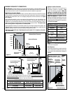
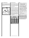
Blocking
Support Straps
(Plumber's tape)
8 feet (2.4 m)
Maximum
1 inch (25.4
mm) minimum
clearance to
combustibles
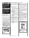
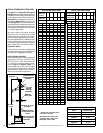
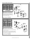
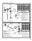
F. Change vent direction to horizontal / inclined
run - At transition from or to a horizontal / in-
clined run, install the SV4.5E45 and SV4.5E90
elbows in the same manner as the straight vent
sections. The elbows feature a twist section to
allow them to be routed about the center axis
of their initial collar section to align with the
required direction of the next vent run element.
Twist elbow sections in a clockwise direction
only so as to avoid the possibility of unlocking
any of the previously connected vent sections.
See Figure 24.
7-5/8”
(194 mm)
4-13/16
(122 mm)
Swivel Joint
(360° swivel)
SV4.5E45
45° Elbow)
Swivel Joint
(360° swivel)
SV4.5E90
90° Elbow)
(206 mm)
8-1/8"
Figure 24
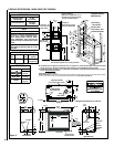
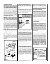
v
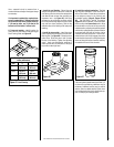
SV4.5VF
Firestop / spacer
uSV4.5SU
Support Strap
8 ft. (2.4 M)
Maximum
uSV4.5SP
Support Plate
Ceiling Framing
uSecured
to Vent with
Appropriate
Fasteners
1” (25.4 mm)
Minimum
Clearance to
Combustibles
vWhen using
secure Flex, use
Firestop/Spacer
SF4.5VF
SV4.5FA or
SV4.5FB Flashing
and SV4.5SC
Storm Collar
SV4.5CGV-1
Termination
Figure 23
16
Figure 22
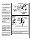
Another method, where the vent is not adjacent
to a wall, is illustrated in Figure 23. Here,
support straps (96K93) and support plates
(96K92) can be used to support the weight
of the vent.
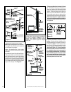
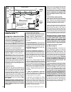
E. Support the vertical vent run sections -
Note - Proper venting support is very important.
The weight of the vent must not be supported
by the fireplace in any degree.
Support the vertical portion of the venting
system every 8 feet (2.4 m) above the fireplace
vent outlet.
One method of support is by utilizing field pro-
vided support straps (conventional plumber's
tape). Secure the plumber's tape to the framing
members with nails or screws. Loop the tape
around the vent, securing the ends of the tape to
the framing. If desired, sheet metal screws #6
x 1/2" length may be used to secure the support
straps to the vent pipe. See Figure 22.
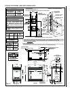
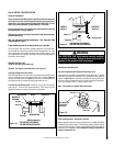
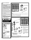
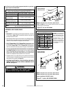
Note: Trim Thimble/
Extension To Desired Length
And Pitch At The Roof Line
14" Min.
Pitched Roof
Pitched Roof
Bow Roof
14" Min.
Outer Pipe Of
Chimney
Outer Pipe Of
Chimney
Outer Pipe Of
Chimney
14" Min.
Firestop
Thimble
Extension
13"
Firestop
Thimble
Firestop
Thimble
Thimble
SV-FSTFE
Figure 21
G. Continue installation of horizontal / inclined
sections - Continue with the installation of the
straight vent sections in horizontal / inclined run
as described in Step C. Install support straps
every 5 feet (1.52 m) along horizontal / inclined
vent runs using conventional plumber’s tape.
See Page 20, Figure 33. It is very important
that the horizontal / inclined run be maintained
in a straight (no dips) and recommended to
be in a slightly elevated plane, in a direction
away from the fireplace of 1/4" rise per foot (20
mm per meter) which is ideal, though rise per
foot run ratios that are smaller are acceptable
all the way down to at or near level.