


NOTE: DIAGRAMS & ILLUSTRATIONS ARE NOT TO SCALE.
24
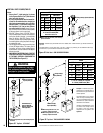
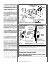
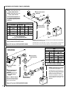
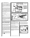
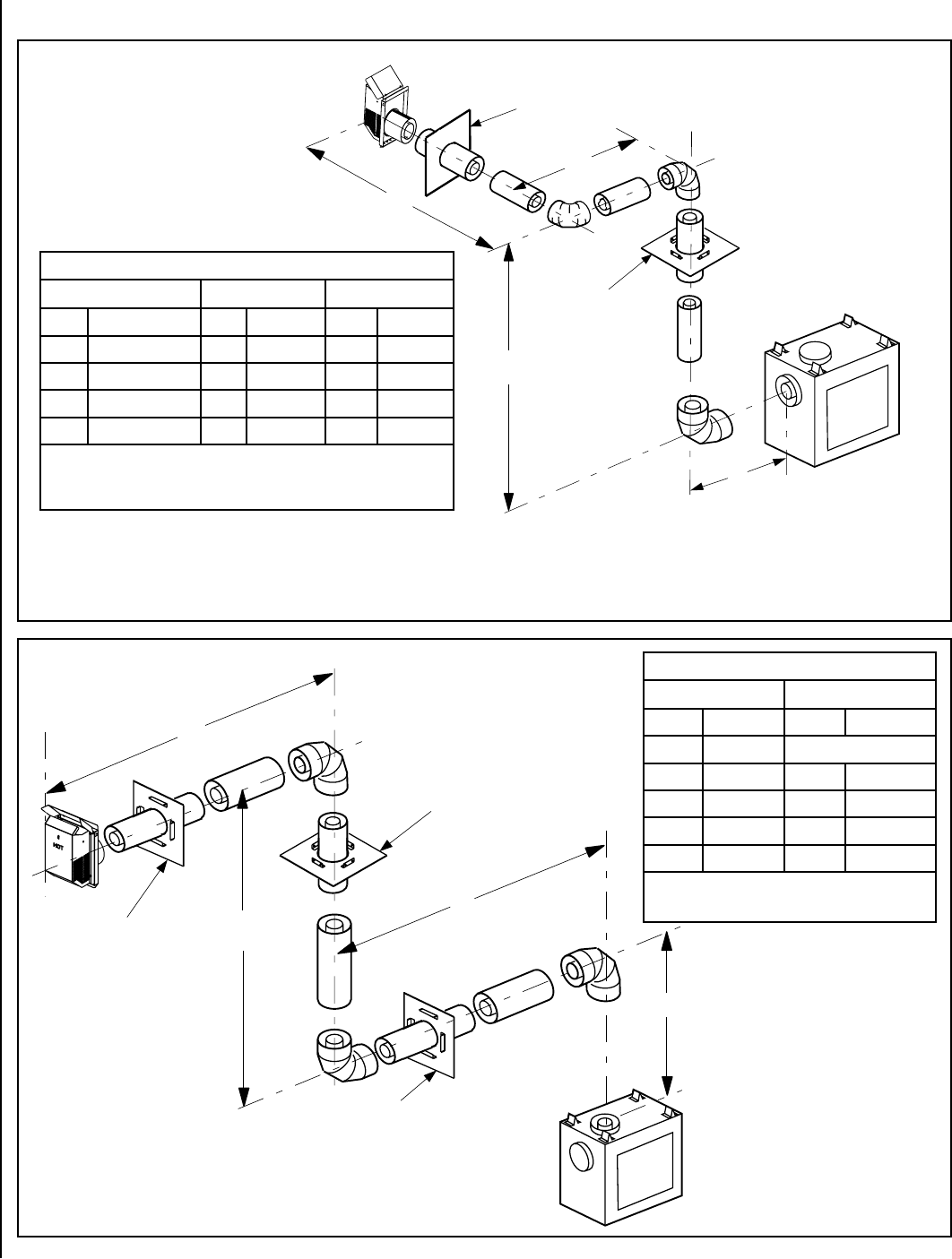
Table I
H
+ H
1
Maximum
V Minimum
feet (meter) feet (meter)
5 (1.524)
Elbow Only
5 (1.524) 1 (0.305)
10 (3.048) 2 (0.610)
15 (4.572) 3 (0.914)
20 (6.096) 4 (1.219)
H
+ H
1
= 20 feet (6.096 m) Max.
V + V
1
+ H + H
1
= 40 ft. (12.192 m) Max.
Example: If 20 feet total (H+H
1
) horizontal
vent run is needed, then 4 feet minimum of
(V) vertical vent will be required.
This table shows a 1(V) to 5(H) ratio. For
every 1 foot of (V) vertical, you are allowed
5 feet of (H+ H
1
) horizontal run, up to a
maximum horizontal run of 20 feet.
An elbow is acceptable as 1 foot of verti-
cal rise except where an elbow is the only
vertical component in the system. See
Figure 37.
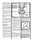
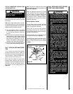
V
H
H
1
V
1
u
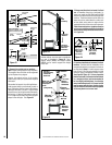
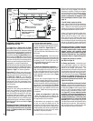
Ceiling Firestop /
Spacer (SV4.5VF)
v
Wall Firestop
/ Spacer (SV4.5HF)
u
When using Secure Flex,
use Firestop / Spacer
SF4.5VF
v
When using Secure Flex,
use Firestop / Spacer
SF4.5HF
Note: See Table 8 on Page 22
as an aid in venting component
selection for a particular range of
exterior wall thicknesses.
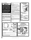
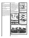
v
Wall Firestop / Spacer
(SV4.5HF)
Square termination
(SV4.5HT-2) shown.
V
H
2
H
1
H
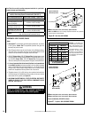
v Wall Firestop / Spacer
(SV4.5HF)
u Ceiling Firestop /
Spacer (SV4.5VF)
u When using Secure Flex, use
Firestop / Spacer SF4.5VF
v When using Secure Flex, use
Firestop / Spacer SF4.5HF
Note: See Table 8 on Page 22 as an
aid in venting component selection
for a particular range of exterior wall
thicknesses.
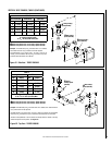
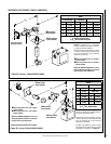
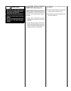
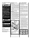
Table H
H
+ H
1
+ H
2
Maximum H
Maximum
V Minimum
feet (meter) feet (meter) feet (meter)
5 (1.524) 2 (0.610) 1 (0.305)
10 (3.048) 4 (1.219) 2 (0.610)
15 (4.572) 6 (1.829) 3 (0.914)
20 (6.096) 8 (2.438) 4 (1.219)
V + H + H
1
+ H
2
= 40 feet (12.2 m) Max
H = 8 feet (2.438 meters) Max.
H + H
1
+ H
2
= 20 feet (6.096 meters) Max.
Example: If 20 feet total (H+H
1
+H
2
) horizontal vent run is needed, then 4 feet minimum
of (V) vertical vent will be required.
This table shows a 1(V) to 5(H) ratio. For every 1 foot of (V) vertical, you are allowed 5
feet of horizontal run up to a maximum total (H+H
1
+H
2
) horizontal run of 20 feet.
Figure 40 - Side Vent, THREE 90 DEGREE ELBOWS
Square termination (SV4.5HT-2) shown
Figure 41- Top Vent, THREE 90 DEGREE ELBOWS
HORIZONTAL VENT FIGURES / TABLES (CONTINUED)