


NOTE: DIAGRAMS & ILLUSTRATIONS ARE NOT TO SCALE.
15
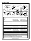
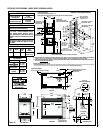
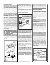
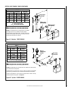
Figure 18
Roof
Framing
Ceiling
Framing
Plumb
Bob
10-1/2" Min.
(267 mm)
10-1/2" Min.
(267 mm)
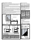
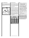
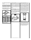
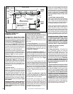
Figure 19
Align the dimple (four places) of the
upper vent section with the opening
of the locking incline channel on the
lower vent section or appliance col-
lar. Twist vent component clockwise
to engage and seal until arrow and
dimple align.
Dimple
Locking Incline
Channel
Connected Vent
Sections
Arrow
Arrow
Appliance Collar or
Vent Section
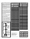
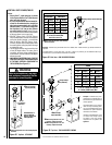
Vertical (Offset) Installation
Analyze the vent routing and determine the
number of vent sections and elbows required.
Refer to Vertical Vent Figures and Tables on
Pages 18 and 19 to select the type of vertical
installation desired. Vent sections are available
in net lengths of 4-1/2" (114 mm), 10-1/2" (267
mm), 22-1/2" (572 mm), 34-1/2" (876 mm) and
46-1/2" (1181 mm). Refer to the Vent Section
Length Charts on Page 14 for an aid in selecting
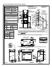
vent length combinations. Elbows are available
in 45° and 90° configurations. Refer to Figure
24 on Page 16 for the SV4.5E45 and SV4.5E90
elbow dimensional specifications.
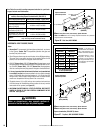
Where required, a Telescopic Vent Section
(SV4.5LA) may be used to provide the installer
with an option in installing in tight and confined
spaces or where the vent run made up of fixed
length pieces develops a joint in a undesirable
location, or will not build up to the required
length. The SV4.5LA Telescopic Vent Section
has an effective length of from 1-1/2" (38 mm)
to 7-1/2" (191 mm). The SV4.5LA is fitted with
a locking inclined channel end (identical to a
normal vent section component) and a plain end
with 3 pilot holes. Slip the plain end over the
locking channel end of a standard SV4.5 vent
component the required distance and secure
with three screws.
Maintain a minimum 1" (25 mm) clearance
to combustible materials for all vertical ele-
ments. Clearances for all horizontal elements
are 3" (76 mm) on top, 1" (25 mm) on sides
and 1" (25 mm) on the bottom.
A. Frame ceiling opening - Use a plumb line
from the ceiling above the appliance to locate
center of the vertical run. Cut and/or frame
an opening, 10-1/2" x 10-1/2" (267 mm x 267
mm) inside dimensions, about this center mark
(Figure 18).
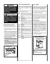
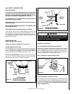
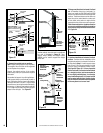
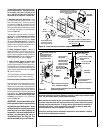
14" Min.
Outer Pipe Of
Chimney
Use correct firestop
thimble depending on the
pitch of the interior
ceiling.
Note: Regular Thimble
(SV-FSTFE) Can Be Used
If A Header Is Constructed
At This Point
Figure 20
Push the vent component against the previous
section until it fully engages, then twist the
component clockwise running the dimples down
and along the incline channels until they seat at
the end of the channels. This seating position
is indicated by the alignment of the arrow and
dimple as shown in Figure 19.
D1. Install firestop/spacer at ceiling between
stories - Install a firestop/spacer (catalog
no. H2247 - Secure Vent; catalog no. H2249
- Secure Flex) at the bottom side of the ceiling
to the ceiling joists. Route the vent sections
through the framed opening and secure the
firestop/spacer with appropriate fasteners at
each corner.
Remember to maintain 1" (25 mm) clear-
ance between vertical chimney sections and
combustibles, framing members, and attic
or ceiling insulation.
D2. Install firestop thimble at the ceiling to
roof location - Position appropriate firestop
thimble (see Table on Page 36) at the bottom
side of ceiling and secure temporarily with
two appropriate fasteners. Attach permanently,
using at least two more fasteners, after vent sec-
tions have been assembled through the firestop
thimble and after any necessary adjustments
have been made.
Ensure the thimble penetrates the roof opening.
The thimble must extend completely through the
ceiling or roof cavity to the outermost plane of
the roof. Use thimble extension SVTE26 when
the distance between the outside of the roof and
the inside of the ceiling exceeds the height of
the firestop thimble. The thimble provides for
zero clearances to combustibles and must be
used at the ceiling/roof in manufactured homes
with Secure Vent double wall vent sections.
Maintain 1 in. (25.4 mm) clearance between
the thimble and the outer pipe of the secure
vent chimney system. See Figure 21 (Page
16) for pitched roofs or flat roofs with flat
ceilings or Figure 20 for pitched roofs with
cathedral ceilings.
To attach a vent component to the appliance
collar, align the dimpled end over the collar,
adjusting the radial alignment until the four lock-
ing dimples are aligned with the inlet of the four
inclined channels on the collar (refer to Figure
19). Push the vent component against the collar
until it fully engages, then twist the component
clockwise, running the dimples down and along
the incline channels until they seat at the end of
the channels. The unitized design of the Secure
Vent components will engage and seal both the
inner and outer pipe without the need for sealant
or screws. If desired a #6 x 1/2" screw may be
used at the joint, but it not required as the pipe
will securely lock when twisted.
Note: An elbow may also be attached to the
appliance collar. Attach in the same manner
as you would a vent section.
C. Attach vent components to each other
- Other vent sections may be added to the
previously installed section in accordance with
the requirements of the vertical vent Figures
and Tables. To add another vent component
to a length of vent run, align the dimpled end
over the inclined channel end of the previously
installed section, adjusting the radial alignment
until the four locking dimples are aligned with
the inlets of the four incline channels of the
previous section.
B. Attach vent components to appliance - Se-
cure Vent SV4.5 direct-vent system compo-
nents are unitized concentric pipe components
featuring positive twist lock connections (see
Figure 19).
All of the appliances covered in this document
are fitted with collars having locking inclined
channels. The dimpled end of the vent com-
ponents fit over the appliance collar to create
the positive twist lock connection.