


NOTE: DIAGRAMS & ILLUSTRATIONS ARE NOT TO SCALE.
10
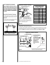
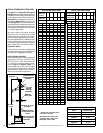
PRODUCT REFERENCE INFORMATION
Cat.
No.
Model Ship
Wt.
Ship.
Volume
H4633 SDVST 282 lbs 52W x 27D x 44-
1/2H (36.2 cu.ft).
Figure 11
NOTES
• Annual Fuel Utilization Efficiency
Diagrams, illustrations and photographs are
not to scale – consult installation instruc-
tions. Product designs, materials, dimen-
sions, specifications, colors and prices are
subject to change or discontinuance without
notice.
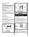
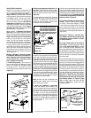
Appliance has a factory-installed vent seal cap
(see Figures 14 and 15 on Page 13) in each
flue outlet.
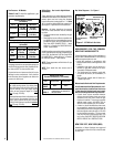
SPECIFICATIONS
Natural & Propane
Gas BTU Input
37,500
(MV Low 30,000)
Co-axial DV Vent Size
4-1/2" Inner
7-1/2" Outer
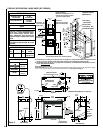
FIREPLACE SPECIFICATIONS - MODEL SDVST (SEE-THROUGH)
EFFICIENCIES
SDVST
61% (NG)
62 % (LP)
Steady State
72 % (NG)
73 % (LP)
• AFUE
68 % (NG)
68 % (LP)
6-7/8
(175)
10-1/4
10-1/2
(260)
12
(305)
12 (305)
10
(254)
(63.5)
3 (76)
FLUE
(Top or Side)
(267)
FLUE
(Top or Side)
GAS INLET
ELECTRICAL
INLETS
GAS INLET
40-1/8
(1019)
(16)
(89)
3
(76)
ELECTRICAL
INLETS
FRAMING SPACERS
(Top and Both Sides)
24
(610)
FINISH WALL BRACKET
(Front and back edge of unit top)
1/2
(13)
3-1/2
3-1/2
(89)
ELECTRICAL
INLETS
(940)
37
41
(1041)
4 (102)
(13)
(1197)
47-1/8
(873)
34-3/8
(610)
24
(63.5)
Detail fo Finish
Wall Bracket
2-1/2
2-1/2
1/2
(13)
1/2
5/8
*41-1/2
(1054)
48-1/2
(1108)
(679)
11-3/8
(267)
(289)
7
(178)
5-1/8
(130)
12-1/8
(308)
10-1/2
22-3/4
(578)
6-1/4
(159)
A
7
(178)
5-1/8
(130)
12-1/8
(308)
26-3/4
Provide additional
space for Side Vent
Seal Cap if installing
against a solid wall.
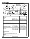
Louvered Control
Compartment Door
Left Side View
Front View
Right Side View
Top View
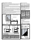
Stepped to Accept Drywall (all 4 corners)
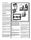
Fireplace Framing
Specifications
**25-1/4
(641)
10-1/2
(267)
12-1/8
(308)
5-1/8
(130)
12-1/8
(308)
26-3/4
(648)
5-1/8
(130)
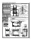
Vent Center - Top
Vent with one 90
degree elbow
Vent Center- Side
Vent (no elbows)
Dimension A
Secure Vent 47-1/8 (1197)
Secure Flex 48-3/4 (1238)
u This dimension can be reduced to 41 inches (1041 mm). This results in 0 in. (0 mm) clearance between framing and unit framing
spacers. (The 41-1/2 in. dimension permits easier fireplace installation, if unit is installed after framing is erected).
v This dimension based on 5/8" drywall. For 1/2" drywall use 25-1/2" (648 mm). The finished dimension should be 26-1/2" (673 mm).
See also, Side Vent Seal Cap note below.
• Inches (millimeters)
•
Minimum Framing Stud Size is 2 x 4
• See
side views of fireplace below
for
gas line inlet location options.
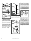
Vent Framing
- Top Vent With
One 90º Elbow
Vent Framing - Rear
Vent With No Elbows
Gas Line Center of gas line is 3 in. (76 mm) up from floor.
Gas
Line
A
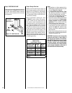
Vertical Venting Through the Ceiling:
Frame ceiling opening - Use a plumb line from the ceiling above the appliance to locate center of the vertical run. Cut and/or frame an opening,
10-1/2" x 10-1/2" (267 mm x 267 mm) inside dimensions, about this center mark (see Figure 18 on Page 15).
v
u