


NOTE: DIAGRAMS & ILLUSTRATION NOT TO SCALE.
8
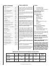
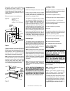
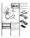
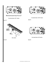
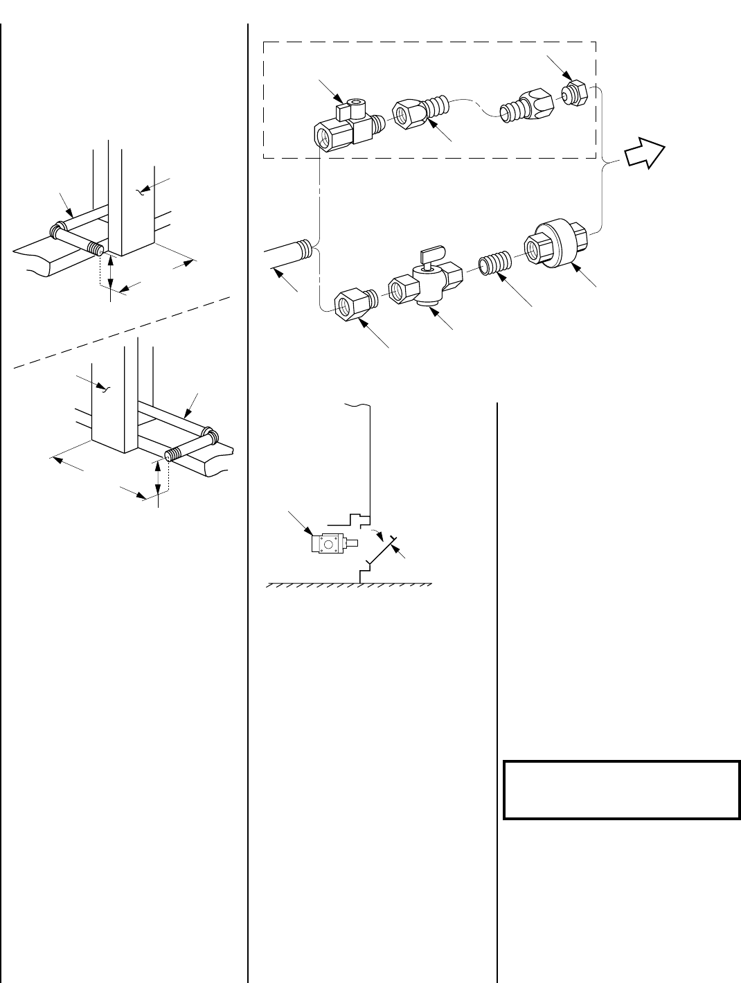
Step 2. Route a ¹⁄₂" (13 mm) gas line along the
left or right side framing (
Figure 9
).
All appliances have a 3" long ³⁄₈" NPT nipple
installed at the valve. To quickly and easily
complete the gas line routing, use the gas flex
line kit, Model GFLV.
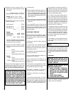
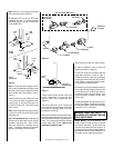
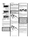
Figure 11
The gas control valve is located in the lower
control compartment. To access the valve
open the lower control compartment door
(
Figure 11
).
The control valve has a ³⁄₈" NPT thread inlet
port and is fitted with two elbows and a nipple
to provide the necessary offset. Plan your
connections accordingly.
Secure all joints tightly using appropriate tools
and sealing compounds (ensure propane resis-
tant compounds are used in propane applica-
tions). Turn on gas supply and test for gas leaks
using a soapy water solution. Never use an
open flame to check for leaks.
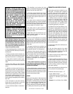
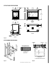
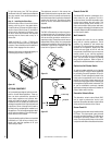
Figure 10
Control
Valve
Lower Control
Compartment Door
Gas Stub
¹₂" x ³₈" Flare
Shut-Off Valve
³₈" Flex Tubing
³₈" NPT x ³₈"
Flare Fitting
³₈" Union
³₈" Close Nipple
³₈" Shut-Off Valve
¹₂" x ³₈" Reducer
Gas Flex Line Kit, Model GFLV
To Appliance
Gas Valve
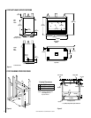
3 ⁷⁄₈"
(98 mm)
4"
(102 mm)
¹⁄₂” Gas
Line
Stud
Plate
Standard
Left Side
11 ³⁄₈"
(289 mm)
4 ¹⁄₈"
(105 mm)
¹⁄₂” Gas
Line
Stud
Plate
Optional
Right Side (ST)
A. Mix a 50% dish soap, 50% water solution.
B. Light the appliance (refer to safety and
lighting instructions on page 15).
C. Brush all joints and connections with the
soapy water solution to check for leaks. If
bubbles are formed, or gas odor is detected,
turn the gas control knob to the “OFF” position.
Either tighten or refasten the leaking connec-
tion and retest as described above.
D. When the gas lines are tested and leak free,
observe the individual tongues of flame on the
burner. Make sure all ports are open and pro-
ducing flame evenly across the burner. If any
ports are blocked, or partially blocked, clean
out the ports.
An external regulator must be used on all pro-
pane (L.P.G.) heaters, in addition to the regula-
tor fitted to the heater, to reduce the supply tank
pressure to 13" w.c. (maximum).
WARNING: CONNECTING DIRECTLY TO
AN UNREGULATED PROPANE TANK CAN
CAUSE AN EXPLOSION.
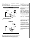
Step 6. Wiring – The wiring diagram is de-
tailed in
Figure 12
. Refer to
Figure 13
to field
wire optional wall switch. All electrical wiring
must be in accordance with local codes or, in
the absence of local codes the latest edition of
the National Electrical Code, ANSI/NFPA 70.
The heater must be electrically grounded.
Figure 9
Step 3. Remove the nailing flanges from the
lower control compartment and install in place
with three (3) screws each. Align with the three
holes on each side of the appliance (
refer to
Figure 5
).
Install the hood on all units. Position the hood
in the open area above the appliance door.
Insert the tabs, on each end of the hood, into
the bracket at each end. Bend the two tabs
over to secure.
Step 4. Position appliance into prepared fram-
ing, secure with 6d nails at the nailing flange
along each side.
Step 5. Connecting Gas Line – Make gas line
connections. All codes require a shut-off valve
mounted in the supply line.
Figure 10
illus-
trates two methods for connecting the gas
supply. Installation methods and materials
must be in compliance with local codes.