


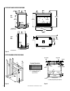
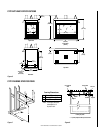

NOTE: DIAGRAMS & ILLUSTRATION NOT TO SCALE.
11
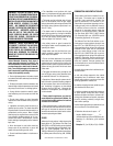
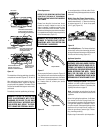
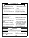
The installation of the logs and twigs, should be
complete and resemble
Figures 15, 16 and 19
.
After setting the logs and rockwool into posi-
tion as described above, ensure the logs are
properly and firmly situated. The heater will not
function as intended if the logs are not correctly
positioned.
Periodically check the positioning of the logs.
WARNING: FAILURE TO POSITION THE
PARTS IN ACCORDANCE WITH THESE
DIAGRAMS OR FAILURE TO USE ONLY
PARTS SPECIFICALLY APPROVED WITH
THIS HEATER MAY RESULT IN PROP-
ERTY DAMAGE OR PERSONAL INJURY.
#1
#2
#3
#6
#4
#7
#5
PORT CLUSTER
B
SPREAD SMALL PIECES OF ROCKWOOL
(A DIME TO A QUARTER SIZE PORTION)
OVER THE SCREEN EXCEPT WHERE NOTED.
DO NOT PUT ANY ROCKWOOL
OVER PORT CLUSTERS.
POSITION THE LOGS ON THE PINS
AS SHOWN. EACH LOG/TWIG IS
IDENTIFIED BY A NUMBER ON THE BACK.
(FRONT)
C
(FRONT)
A
(FRONT)
PLACE THIS END OF TWIG BETWEEN
TWO PORT CLUSTERS ON TOP OF
PIN ON BURNER AS SHOWN.
PLACE THIS END OF THE
TWIG ON TOP OF PIN ON
BURNER AS SHOWN.
Figure 16
Flame Appearance
REFER TO THE OPERATING INSTRUCTIONS
LOCATED AT THE BACK OF THIS MANUAL
BEFORE LIGHTING THE HEATER TO OBSERVE
THE FLAMES.
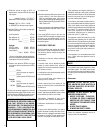
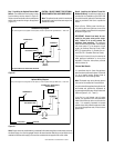
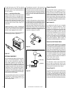
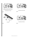
Flames from the pilot, front and rear burner
should be visually checked as soon as the
heater is installed. In addition a periodic visual
check of the flames should be made. The pilot
flame should always be present when the heater
is in operation and should just envelope the tip
of the thermocouple (
Figure 17
).
WARNING: NO ADJUSTMENTS ARE TO
BE MADE TO THE ODS PILOT SYSTEM.
TAMPERING WITH THIS SYSTEM CAN
BE EXTREMELY HAZARDOUS.
Figure 17
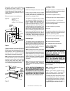
An incorrect pilot flame is shown in
Figure 18
.
This pilot flame will cause the thermocouple to
cool. When the thermocouple cools, the heater
will shut off. If pilot flame pattern is incorrect,
or if heater shuts off, contact your service
representative.
Propane Shown
Figure 18
Propane Shown
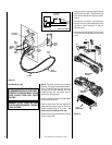
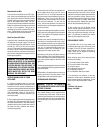
In normal operation, at full rate, after 15 min-
utes the following flame appearance should be
observed:
Middle Ember Bed Flame Characteristics –
The rear flames should be yellow. The flames
should extend about 3 – 4" above the front log
for natural gas and 2 – 3" above for propane
(L.P.G.) gas (
Figure 19
).
Figure 19
Left and Right Burner – The flames at the front
burner holes will be blue becoming yellowish
as they hit the bark-like texture of the base and
front face of the front log (
Figure 19
).
Appliance Operation
WARNING: THE LOWER CONTROL COM-
PARTMENT AREA AND LOWER CONTROL
COMPARTMENT ACCESS DOOR ARE EX-
TREMELY HOT WHEN THE APPLIANCE IS
IN OPERATION. EXERCISE EXTREME CARE
WHEN ACCESSING THIS AREA. TOUCH
ONLY THE FAR ENDS OF THE LOWER
CONTROL COMPARTMENT DOOR WHEN
OPENING WHILE THE APPLIANCE IS HOT.
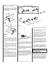
Step 10. Checking the System – With gas line
installed run initial system checkout before
closing up the front of the unit. Follow the pilot
lighting instructions on page 15.
Note: Instructions are also found on the pull
out panel located on the bottom surface of the
appliance.
When first lighting the appliance, it will take a
few minutes for the line to purge itself of air.
Once purging is complete, the pilot and burner
will light and operate as indicated in the in-
struction manual. Subsequent lightings of the
appliance will not require such purging. In-
spect the pilot flame (remove logs, if neces-
sary, handling carefully).
Replace logs if removed for pilot inspection.