


18
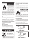
4. Do not plug in power cord until vent system is completely installed.
The Power Vent operates on 120 Vac, therefore a grounded outlet
must be within reach of the 6 foot exible power cord supplied
with the vent. The power cord supplied may be used on unit
only where local codes permit. If local codes do not permit use
of exible power supply cord:
A. Remove screws that hold cover plate on control box and
remove plate.
B. Cut exible power cord on inside of control box, as close to
inside wall as possible.
C. If exible cord and strain relief are removed, then opening
in box must be covered by a plastic cap on the front side of
the control box.
D. Remove plastic cap on the right side of control box and install
suitable conduit tting in enclosure.
E. Splice eld wiring into existing wiring using code authorized
method (wire nuts, etc.).
F. Be certain that neutral and line connections are not reversed
when making these connections.
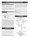
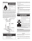
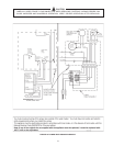
G. Ground heater properly. This water heater must be grounded
in accordance with the National Electrical Code ANSI/
NFPA70 and/or local codes. These must be followed in all
cases.
The water heater must be connected to a grounded metal,
permanent wiring system; or an equipment grounding
conductor must be run with the circuit conductors and
connected to the equipment grounding terminal or lead on
the water heater, see Figure 19.
H. Replace cover plate and secure with two screws.
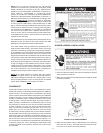
5. The blower discharge boot is made to accept only straight
sections of 3” pipe. To start off with an elbow, a short section
of the furnished pipe, a minimum of 2 inches, must be cut and
glued into the end of the elbow that will mount on the discharge
boot (see gure 16).
INSTALLATION OF VENT SYSTEM
Before beginning installation of piping system thoroughly read the
section of this manual VENT PIPE PREPARATION.
If you are installing your system so that it vents through the roof, please
refer to section titled INSTALLATION OF VERTICAL VENT SYSTEM.
VENT TERMINAL INSTALLATION, SIDEWALL
1. Install the vent terminal by using the cover plate as a template to
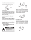
mark the hole for the vent pipe to pass through the wall. BEWARE
OF CONCEALED WIRING AND PIPING INSIDE THE WALL.
2. If the Vent Terminal is being installed on the outside of a nished
wall, it may be easier to mark both the inside and outside wall.
Align the holes by drilling a hole through the center of the template
from the inside through to the outside. The template can now be
positioned on the outside wall using the drilled hole as a centering
point for the template.
3. A) MASONRY SIDE WALLS
Chisel an opening approximately one half inch (1.3 cm) larger
than the marked circle.
B) WOODEN SIDE WALLS
Drill a pilot hole approximately one quarter inch (0.64 cm) outside
of the marked circle. This pilot hole is used as a starting point
for a saws-all or sabre saw blade. Cut around the marked circle
staying approximately one quarter inch (0.64 cm) outside of the
line. (This will allow the vent to easily slide through the opening.
The resulting gap will be covered up by the Vent Terminal cover
plate.) Repeat this step on inside wall if necessary.
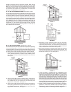
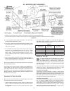
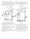
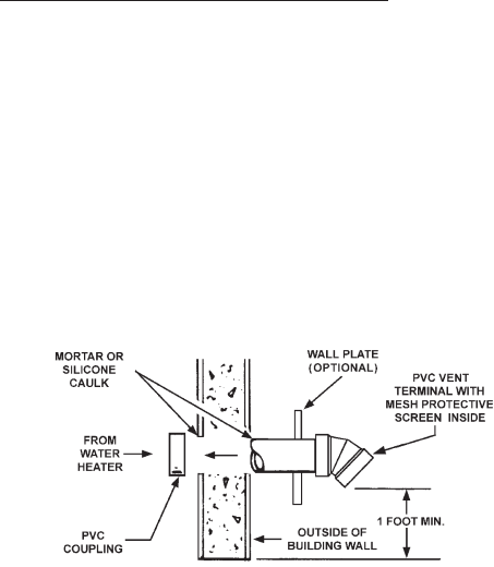
SEQUENCE OF INSTALLATIONS, FIGURE 17
Cut a length of PVC pipe about 3.5 inches (8.9 cm) longer than the
wall thickness at the opening. Glue the vent terminal to this section
of pipe. Slide the wall plate over the pipe to stop against the vent
terminal. Place a bead of caulking (not supplied) around the gap
between the pipe and cover plate. Apply enough to ll some of the
gap between the pipe and wall. Place some of the caulking on the
back of the plate to hold it against the wall after installation. If the
vent pipe is installed up to the wall, with a coupling on the end against
the wall opening, the pipe with the vent terminal can be prepared
for gluing before inserting through the wall. Slide the pipe through
the wall and insert into the coupling on the other side of the wall,
making sure that the vent terminal ends up pointed in the correct
position, see Figure 17.
FIGURE 17. VENT TERMINATION