


16
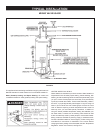
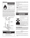
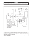
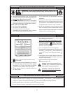
2. A venting system should terminate at least 3 feet above any
forced air inlet located within 10 feet.
3. The venting system should terminate at least 4 feet below, 4 feet
horizontally from or, 1 foot above any door, window or gravity air
inlet into any building.
4. The manufacturer also recommends that the vent system
termination not be installed closer than 18” from an inside
corner of an L shaped structure and not be less than 1 foot
above grade. The vent should terminate a minimum of 12’’
above expected snowfall level to prevent blockage of vent
termination.
5. The vent termination should not be mounted directly above or
within 3 feet horizontally from an oil tank vent or gas meter to
avoid potential freeze-up from condensation.
Plan the vent system layout so that proper clearances are maintained
from plumbing and wiring.
Vent pipes serving power vented appliances are classified by
building codes as “vent connectors”. Required clearances from
combustible materials must be provided in accordance with
information in this manual under LOCATION OF HEATER and
INSTALLATION OF VENT SYSTEM, and with the National Fuel
Gas Code and local codes.
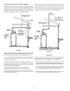
PLANNING THE VENT SYSTEM
Plan the route of the vent system from the discharge of the blower
to the planned location of the vent terminal.
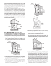
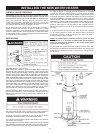
1. Layout the total vent system to use a minimum of vent pipe and
elbows. Take into consideration that an elbow will be necessary
to make the rst vent pipe connection to the power venter outlet,
see Figure 6.
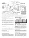
2. This water heater is capable of venting the ue gases the
equivalent of thirty (30) feet of 3 inch pipe or one-hundred (100)
feet of 4 inch pipe as listed in Table 1.
TABLE 1.
Number of 3” Maximum 4” Maximum
90° Elbows Pipe (Feet) Pipe Feet
ONE (1) 25 92
TWO (2) 20 84
THREE(3) 15 76
FOUR (4) 10 68
FIVE (5) - - - 60
Minimum of one (1) elbow and 2 feet of straight pipe must be
installed for 3” and 4” pipe.
NOTE: The equivalent feet of pipe listed above are exclusive
of the “45° Elbow” termination. That is, the termination “45°
Elbow”, with installed screen, is assumed to be in the system
and the remainder of the system must not exceed the thirty (30)
equivalent feet of 3 inch pipe or one-hundred (100) equivalent
feet of 4 inch pipe.
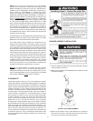
3. The blower discharge adapter is made to accept only straight
sections of 3” pipe. To start a minimum of 2 inches of 3” pipe
must be attached to the blower discharge. See Figure 6.
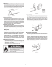
If using 3 inch vent pipe:
A minimum of 2 inches, maximum of 4 feet of 3” pipe must be
attached to the blower before the rst 3-inch elbow. After the rst
elbow add the additional venting required for the installation. The
total system cannot exceed 30 equivalent feet of venting, where
each elbow is equal to 5 feet of straight pipe.
If using 4 inch vent pipe:
Two inches of 3” pipe must be attached to the blower discharge.
A 4” x 3” reducer is added and then up to maximum 4 feet of
4 inch pipe added before the rst elbow. An additional 4” x 3”
reducer and (1) foot of 3” pipe must be added to the end of the
vent system before terminating into the 3” 45° elbow. The total
system cannot exceed 100 equivalent feet of 4” venting, where
each elbow is equal to 8 feet of straight pipe.
FIGURE 15.
U.S. HORIZONTAL VENT CLEARANCES
WARNING
VENT HOOD(S) MAY BE
EXTREMELY HOT
DURING OPERATION.