


10
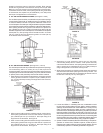
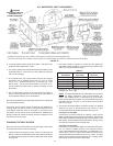
Minimum clearances between the water heater and combustible
construction are 0 inch at the sides and rear, 5.5” (14.0 cm) from the
front and 12” (30.5 cm) from the top (standard clearance). If clearances
stated on the heater differ from standard clearances, install water
heater according to clearances stated on the heater.
Adequate clearance 24” (61.0 cm) for servicing this appliance should
be considered before installation, such as changing the anodes, etc.
A minimum clearance of 5.5” (14.0 cm) must be allowed for access to
replaceable parts such as the thermostats, drain valve and relief valve.
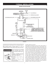
When installing the heater, consideration must be given to proper
location. Location selected should be as close to the wall as practicable
and as centralized with the water piping system as possible.
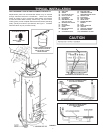
FIGURE 3. FIGURE 4.
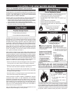
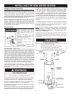
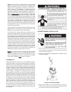
A gas water heater cannot operate properly without the correct amount
of air for combustion. Do not install in a conned area such as a closet,
unless you provide air as shown in the “Locating The New Water
Heater” section. Never obstruct the ow of ventilation air. If you have
any doubts or questions at all, call your gas supplier. Failure to provide
the proper amount of combustion air can result in a re or explosion
and cause death, serious bodily injury, or property damage.
FIGURE 5.
If this water heater will be used in beauty shops, barber shops, cleaning
establishments, or self-service laundries with dry cleaning equipment, it
is imperative that the water heater or water heaters be installed so that
combustion and ventilation air be taken from outside these areas.
Propellants of aerosol sprays and volatile compounds (cleaners,
chlorine based chemicals, refrigerants, etc.), in addition to being highly
ammable in many cases, will also react to form corrosive hydrochloric
acid when exposed to the combustion products of the water heater.
The results can be hazardous, and can also cause product failure.
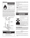
INSULATION BLANKETS
Insulation blankets are available to the general public for external use
on gas water heaters but are not necessary with these products. The
purpose of an insulation blanket is to reduce the standby heat loss
encountered with storage tank heaters. Your water heater meets or
exceeds the Energy Policy Act standards with respect to insulation and
standby loss requirements, making an insulation blanket unnecessary.
Should you choose to apply an insulation blanket to this heater, you
should follow these instructions (for identication of components
mentioned below, see Figure 1). Failure to follow these instructions
can restrict the air ow required for proper combustion, potentially
resulting in re, asphyxiation, serious personal injury, or death.
• Do not apply insulation to the top of the water heater, as this will
interfere with safe operation of the blower assembly.
• Do not cover outer door,
thermostat or temperature & pressure
relief valve.
• Do not allow insulation to come within 2” (5.1 cm) of the oor to
prevent blockage of combustion air ow to the burner.
• Do not cover the instruction manual. Keep it on the side of the
water heater or nearby for future reference.
• Do obtain new warning and instruction labels from the manufacturer
for placement on the blanket directly over the existing labels.
• Do inspect the insulation blanket frequently to make certain it
does not sag, thereby obstructing combustion air ow.
COMBUSTION AIR AND VENTILATION FOR
APPLIANCES LOCATED IN UNCONFINED SPACES
UNCONFINED SPACE is space whose volume is not less than
50 cubic feet per 1,000 Btu per hour (4.8 cubic meters per kW) of the aggregate
input rating of all appliances installed in that space. Rooms communicating
directly with the space in which the appliances are installed, through openings
not furnished with doors, are considered a part of the unconned space.
In unconned spaces in buildings, inltration may be adequate to
provide air for combustion, ventilation and dilution of ue gases.
However, in buildings of tight construction (for example, weather
stripping, heavily insulated, caulked, vapor barrier, etc.), additional air
may need to be provided using the methods described in “Combustion
Air and Ventilation for Appliances Located in Conned Spaces.”
COMBUSTION AIR AND VENTILATION FOR
APPLIANCES LOCATED IN CONFINED SPACES
CONFINED SPACE is a space whose volume is less than 50 cubic
feet per 1,000 Btu per hour (4.8 cm per kW) of the aggregate input
rating of all appliances installed in that space.
When drawing combustion air from inside a conventionally
constructed building to a conned space, such a space should be
provided with two permanent openings. ONE WITHIN 12 INCHES
(30 cm) OF THE ENCLOSURE TOP AND ONE WITHIN 12 INCHES
(30 cm) OF THE ENCLOSURE BOTTOM. Each opening should have
a free area of one square inch per 1000 Btu/hr (22 cm
2
/kW) of the
total input of all appliances in the enclosure, but not less than 100
square inches (645 cm
2
). If the conned space is within a building of
tight construction, air for combustion and ventilation must be obtained
from outdoors. When directly communicating with the outdoors or
communicating through vertical ducts, two permanent openings,