


17
NOTE: This unit can be vented using only the following
materials: PVC (Cellular Core; ASTM-F891), PVC (DWV; ASTM
D2665 or CSA B181.2), PVC (Sch 40, 80, 120; ASTM D1785 or
CSA B137.3), PVC (SDR Series; ASTM-D2241 or CSA B137.3),
CPVC (CPVC 41; ASTM-D2846 or CSA B137.6), CPVC
(Sch 40, 80; ASTM-F441 or CSA B137.6), CPVC (SDR Series;
ASTM-F442), ABS (Sch 40 DWV; ASTM D2661 or CSA B181.1),
ABS (Sch 40 DWV cellular core; ASTM-F628). The ttings, other
than the TERMINATION should be equivalent to PVC-DWV
ttings meeting ASTM D-2665 (Use CPVC ttings, ASTM F-438
for CPVC pipe and ABS ttings, ASTM D-2661/3311 for ABS
pipe). If CPVC or ABS pipe and ttings are used, then the proper
cement must be used for all joints, including joining the pipe to
the Termination (PVC Material). If local codes do not allow the
use of the PVC termination when a material other than PVC is
used for venting, then an equivalent tting of that material may
be substituted if the screen in the PVC terminal is removed and
inserted into the new tting.
PVC Materials should use ASTM D-2564 Grade Cement; CPVC
Materials should use ASTM F-493 Grade Cement and ABS
Materials should use ASTM D-2235 Grade Cement.
If the water heater is being installed as a replacement for an
existing power vented heater in pre-existing venting, a thorough
inspection of the existing venting system must be performed prior
to any installation work. Verify that the correct material as detailed
above has been used, and that the minimum or maximum vent
lengths and terminal location as detailed in this manual have been
met. Carefully inspect the entire venting system for any signs of
cracks or fractures, particularly at the joints between elbows and
other ttings and the straight runs of vent pipe. Check the system
for signs of sagging or other stresses in the joints as a result of
misalignment of any components in the system. If any of these
conditions are found, they must be corrected in accordance with
the venting instructions in this manual before completing the
installation and putting the water heater into service.
NOTE: A. For water heaters in locations with high ambient
temperatures (above 100°F) it is recommended that CPVC or
ABS pipe and ttings be used. B. A 22.5 degree elbow (2” vent
pipe) or a 45 degree elbow (3” and 4” vent pipe) with an installed
screen VENT TERMINAL must be used in all cases.
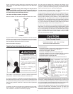
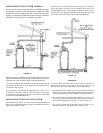
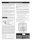
CONDENSATE
Condensate formation does not occur in all installations of power
vented water heaters, but should be protected against on installations
where it can form in the venting system. Condensation in the venting
system of power vented water heaters is dependent upon installation
conditions including, but not limited to ambient temperature and
humidity of installation location, ambient temperature and humidity
of venting space, vent discharge and slope, and product usage. In
certain conditions, installations in unconditioned space or having
long horizontal or vertical vent runs may accumulate condensate.
In these conditions, the vent pipe should be sloped downward
away from the blower assembly (not less than 1/8” (3.2 mm) nor
greater than 1/2” (12.7 mm) per foot maximum). If the vent piping
is vented level or sloped upwards away from the blower assembly,
then adequate means for draining and disposing of the condensate
needs to be made by the installer (if condensate is detected). If you
have condensate, then a 3/8” drain hose can be connected to the
built-in drain port of the rubber boot on the blower assembly. For
your convenience, the rubber boot is supplied with a removable cap
on the built-in drain port. Prior to operating the water heater, make
sure the removable cap is installed on the drain port (if a drain hose
is not needed).
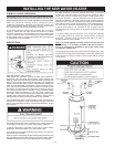
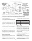
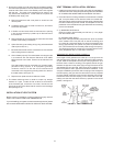
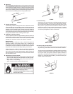
BLOWER ASSEMBLY INSTALLATION
1. Check to make sure that the wire harness is attached to the gas
valve and blower control box.
2. Make sure no material is still attached to the outside or inside
of blower assembly.
FIGURE 16. BLOWER ASSEMBLY
3. Make sure that plastic tubing is still attached to the pressure
switch and fan housing. Also make sure that wiring connector
from motor to control box is securely attached.