


11
located in the above manner, should be provided. Each opening
should have a free area of not less than one square inch per 4000
Btu/hr (5.5 cm
2
/kW) of total input of all appliances in the enclosure.
If horizontal ducts are used, each opening should have a free area
of not less than one square inch per 2000 Btu/hr (11cm
2
/kW) of the
total input of all appliances in the enclosure.
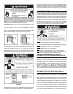
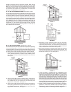
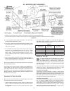
A. ALL AIR FROM INSIDE BUILDINGS: (See Figure 5 and 6)
The conned space should be provided with two permanent openings
communicating directly with an additional room(s) of sufcient volume
so that the combined volume of all spaces meets the criteria for an
unconned space. The total input of all gas utilization equipment installed
in the combined space should be considered in making this determination.
Each opening should have a minimum free area of one square inch
per 1,000 Btu per hour (22 cm
2
/kW) of the total input rating of all gas
utilization equipment in the conned space, but not less than 100 square
inches (645 cm
2
). One opening should commence within 12 inches
(30 cm) of the top and one commencing within 12 inches (30 cm)
of the bottom of the enclosures.
FIGURE 6.
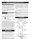
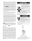
B. ALL AIR FROM OUTDOORS: (See Figures 7, 8 and 9)
The conned space should be provided with two permanent openings,
one commencing within 12 inches (30 cm) of the top and one
commencing within 12 inches (30 cm) from the bottom of the enclosure.
The openings should communicate directly, or by ducts, with the outdoors
or spaces (crawl or attic) that freely communicate with the outdoors.
1. When directly communicating with the outdoors, each opening should
have a minimum free area of 1 square inch per 4,000 Btu per hour
(5.5 cm
2
/kW) of total input rating of all equipment in the enclosure,
see Figure 7.
FIGURE 7.
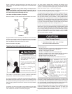
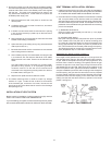
2. When communicating with the outdoors through vertical ducts,
each opening should have a minimum free area of 1 square inch
per 4,000 Btu per hour (5.5 cm
2
/kW) of total input rating of all
equipment in the enclosure, see Figure 8.
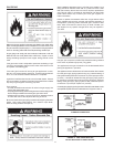
3. When communicating with the outdoors through horizontal ducts,
each opening should have a minimum free area of 1 square inch
per 2,000 Btu per hour (11 cm
2
/kW)) of total input rating of all
equipment in the enclosure, see Figure 9.
FIGURE 8.
FIGURE 8B.
5. Alternatively a single permanent opening may be used when
communicating directly with the outdoors, or with spaces that freely
communicate with the outdoors. The opening shall have a minimum free
area of 1 square inch per 3,000 BTU per hour (8.3 cm
2
/kW) of total input
rating of all equipment in the enclosure. See Figure 8B.
4. When ducts are used, they should be of the same cross-sectional
area as the free area of the openings to which they connect. The
minimum short side dimension of rectangular air ducts should not
be less than 3 inches (7.6 cm), see Figure 9.
FIGURE 9.
5. Louvers and Grilles: In calculating free area, consideration should
be given to the blocking effect of louvers, grilles or screens protecting
openings. Screens used should not be smaller than 1/4 inch (6.4 mm)
mesh. If the free area through a design of louver or grille is known, it
should be used in calculating the size opening required to provide the
free area specied. If the design and free area is not known, it may be
assumed that wood louvers will be 20-25 percent free area and metal
louvers and grilles will have 60-75 percent free area. Louvers and grilles
should be xed in the open position or interlocked with the equipment
so that they are opened automatically during equipment operation.
6. Special Conditions Created by Mechanical Exhausting or Fireplaces:
operation of exhaust fans, ventilation systems, clothes dryers or
replaces may create conditions requiring special attention to avoid
unsatisfactory operation of installed gas utilization equipment.