


ULTRA HIGH EFFICIENCY POWER VENT/POWER DIRECT VENT - SERVICE MANUAL
Technical Literature Department 48 of 52 Ashland City, TN © 2008
Servicing should only be performed by a Qualified Service Agent
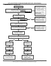
FAULT MESSAGES (CONT)
DISPLAYED MESSAGE
CONDITION/INDICATES
CHECK/REPAIR
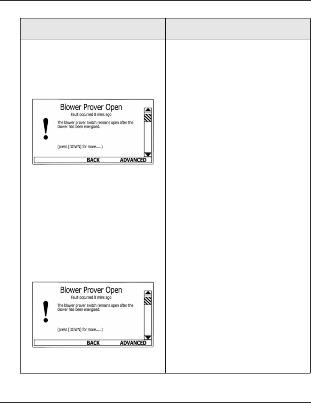
“Blower Prover Open”
(Blower Not Running)
The control system has detected open contacts at
the Blower Prover air pressure switch after Blower
has been energized.
PERFORM ALL THESE TESTS WITH POWER
TURNED ON AND A CALL FOR HEAT ACTIVE.
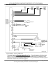
• Check for 120 VAC at the CCB’s J2 Socket
(page 36) pins 1 & 2. Perform close visual
inspection of the pins inside the plug and socket
- ensure plugs and sockets are mating properly
and providing good contact.
• Check all wiring between CCB’s J2 Socket pins
1 & 2 and the blower motor assembly’s high
voltage 3 Pin Socket (see page 10).
• Disconnect the plug at the blower motor assem-
bly’s high voltage 3 Pin Socket - check for 120
VAC at the plug end.
• Perform close visual inspection of the pins
inside the plug and socket at the blower motor
assembly’s high voltage 3 Pin Socket - ensure
plugs and sockets are mating properly and pro-
viding good contact.
• Disconnect the plug at the blower assembly’s
Low Voltage PWM 5 pin plug (see page 10). If
the Blower has not been running prior and starts
running when this plug is disconnected - call the
technical support phone number shown on the
water heater labeling for further assistance.
“Blower Prover Open”
(Blower Is Running)
The control system has detected open contacts at
the Blower Prover air pressure switch after Blower
has been energized.
• Ensure the Blower Prover air pressure switch
sensing tube is connected properly at both ends
and that it is not kinked or damaged. Repair/
replace anything worn or damaged as neces-
sary.
• Check all wiring between CCB’s J6 Socket
(page 35) pins 6 & 7 and the Blower Prover air
pressure switch. Repair/replace anything worn
or damaged as necessary.
• Perform close visual inspection of the pins
inside the CCB J6 plug and socket - ensure
plugs and sockets are mating properly and pro-
viding good contact.
• Review the air pressure switch information
beginning on page 18. Perform the pressure
switch test procedure for the Blower Prover air
pressure switch - see pages 21 through 23.
Replace the Blower Prover switch if defective.