


Technical Literature Department 47 of 52 Ashland City, TN © 2008
Servicing should only be performed by a Qualified Service Agent
ULTRA HIGH EFFICIENCY POWER VENT/POWER DIRECT VENT - SERVICE MANUAL
FAULT MESSAGES (CONT)
DISPLAYED MESSAGE
CONDITION/INDICATES
CHECK/REPAIR
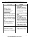
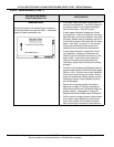
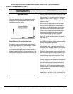
“Blocked Exhaust Vent”
The control system has detected open contacts at
the Blocked Exhaust air pressure switch - the water
heater is not venting properly.
• Check for restrictions, too many equivalent feet,
or too many elbows in the vent pipe. Ensure
• Review venting installation section of the
Instruction Manual that came with the water
heater - see Table 1 on page 7 in this manual.
Ensure the vent/intake air piping has been
installed within manufacturers requirements.
• Check all wiring between the Blocked Exhaust
air pressure switch and the CCB’s J6 Socket
(page 36) pins 5 & 10. Perform close visual
inspection of the pins inside the plug and socket
- ensure plugs and sockets are mating properly
and providing good contact. Repair/replace any-
thing worn or damaged.
• Review the air pressure switch information
beginning on page 18. Perform the pressure
switch test procedure for the Blocked Exhaust
air pressure switch - see pages 21 through 23.
Replace the Blocked Exhaust switch if defec-
tive.
• Call the technical support phone number shown
on the water heater labeling for further assis-
tance if the problem has not been corrected
after performing the procedures outlined here.
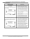
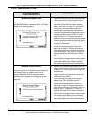
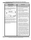
“Blower Prover Failure”
The control system has detected closed contacts at
the Blower Prover air pressure switch out of
sequence. Blower Prover air pressure switch
contacts should be open at the beginning of each
heating cycle - see the Sequence of Operation on
page 40.
• Check all wiring between the Blower Prover air
pressure switch and the CCB’s J6 Socket (page
36) pins 6 & 7. Ensure there are no shorted or
pinched wires.
• Ensure there are no jumper wires installed on
the Blower Prover switch.
• Ensure there are no jumper wires installed
between the CCB’s J6 Socket pins 6 & 7.
• Review the air pressure switch information
beginning on page 18. Perform the pressure
switch test procedure for the Blower Prover air
pressure switch - see pages 21 through 23.
Replace the Blower Prover switch if defective.
• Call the technical support phone number shown
on the water heater labeling for further assis-
tance if the problem has not been corrected
after performing the procedures outlined here.