


Technical Literature Department 15 of 52 Ashland City, TN © 2008
Servicing should only be performed by a Qualified Service Agent
ULTRA HIGH EFFICIENCY POWER VENT/POWER DIRECT VENT - SERVICE MANUAL
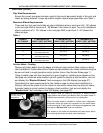
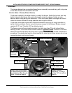
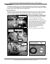
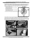
GAS VALVE
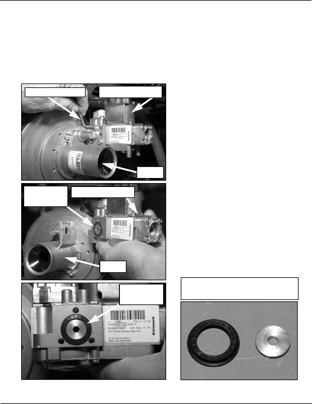
The outlet of the gas valve is connected by flange directly to the side of the Venturi (page
14). There is no manifold gas line on the water heater. A gas orifice with gasket is fitted into
the gas valve’s outlet flange. See the images below.
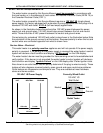
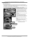
Gas Valve Removal
The gas valve must be removed to inspect the gas orifice. There are 3 - 5/32” hex head
screws that secure the gas valve to the Venturi. Long T handle hex wrenches (8-10”) will
save considerable time when removing/installing the gas valve, blower and burner.
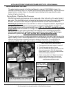
5/32” hex wrench
Gasket Orifice
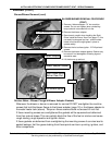
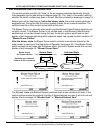
Natural Gas Orifice 0.191”
Propane Gas Orifice 0.162”
Venturi
Gas Orifice
& Gasket
24 VAC Gas Valve
Gas Orifice
& Gasket
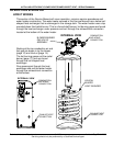
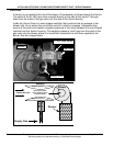
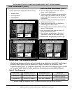
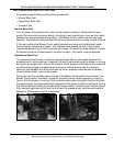
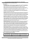
GAS VALVE REMOVAL PROCEDURE
1 Ensure power to the water heater is turned off.
2 Turn off the supply gas shut off valve.
3 Disconnect supply gas line to water heater.
4 Remove 3 gas valve mounting screws - 5/32” hex
head machine screws. Support gas valve body
when removing last screw. Long T handle hex
wrenches (8-10”) will save considerable time
when removing/installing the gas valve.
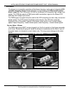
5 Carefully lift gas valve body off of flange
connection on Venturi.
6 Gas orifice and gasket are now accessible.
Venturi
24 VAC Gas Valve