


ULTRA HIGH EFFICIENCY POWER VENT/POWER DIRECT VENT - SERVICE MANUAL
Technical Literature Department 38 of 52 Ashland City, TN © 2008
Servicing should only be performed by a Qualified Service Agent
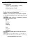
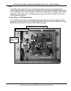
CCB (CONT)
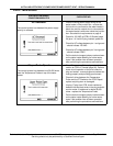
J7 Socket - Temperature Probe/ECO (immersion probe - top of the water heater)
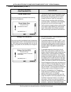
J9 Port - Communication Port - Not Used
J10 Socket - Not Used
J11 Port - Communication Port - Not Used
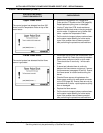
J13 Socket - Blower Speed Control (VFD)
J15 Socket - Not Used
J16 Port - Communication Port - UIM Display (user interface module)
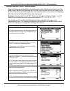
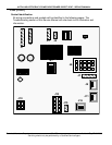
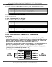
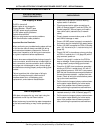
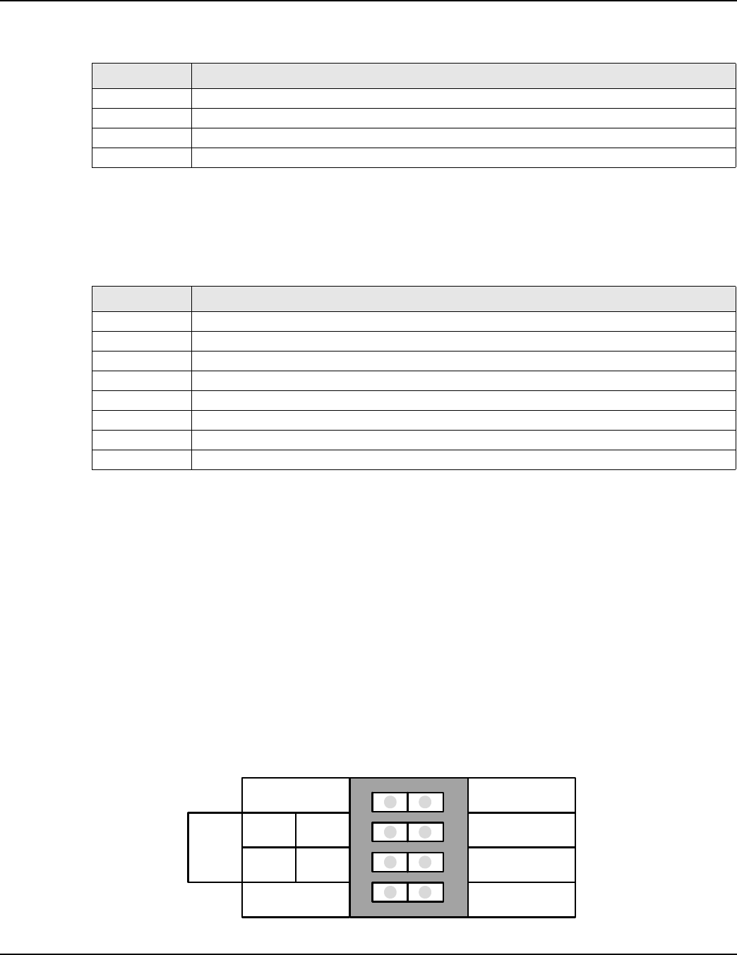
S1 Dip Switch
The S1 dip switches are configured from the factory and should not be changed. The
illustration below shows the 4 dip switches with labeling. Dip switches are toggle type micro
switches. Flipping a dip switch towards “Open” would be the same as “Off.” Flipping a dip
switch the other way (towards the switch numbers) is the same as “On.”
Dip switch #1 is used to configure the water heater to declare a fault condition and lock out
after one or three failed trials for ignition. The factory setting is “on” for three trials.
Dip switches #2 and #3 are used when this control system is installed on other products.
The factory setting for these two dip switches is “on.”
Dip switch #4 is a spare, configuration does not matter.
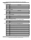
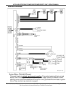
PIN # DESCRIPTION
1 ECO (energy cut out) 24 VAC out (red wire)
2 Upper temperature probe (thermistor) +5.0 VDC (black wire)
3 Upper temperature probe (thermistor) -5.0 VDC (black wire)
4 ECO (energy cut out) 24 VAC return (red wire)
PIN # DESCRIPTION
1 Not used
2 Not used
3 To Blower low voltage PWM plug (see page 10) - pin #5 (white w/grn stripe)
4 Not used
5 Not used
6 Not used
7 To Blower low voltage PWM plug (see page 10) - pin #4 (white w/blue stripe)
8 To Blower low voltage PWM plug (see page 10) - pin #1 (white w/brn stripe)
OPEN
1 2 3 4
1 Retry
Use Yes
Type Tstat
Spare
Ext
Input
3
Retries
No
Vent
Spare
ON
CLOSED
OFF
OPEN