


Technical Literature Department 19 of 52 Ashland City, TN © 2008
Servicing should only be performed by a Qualified Service Agent
ULTRA HIGH EFFICIENCY POWER VENT/POWER DIRECT VENT - SERVICE MANUAL
AIR PRESSURE SWITCHES (CONT)
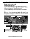
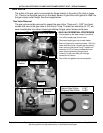
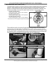
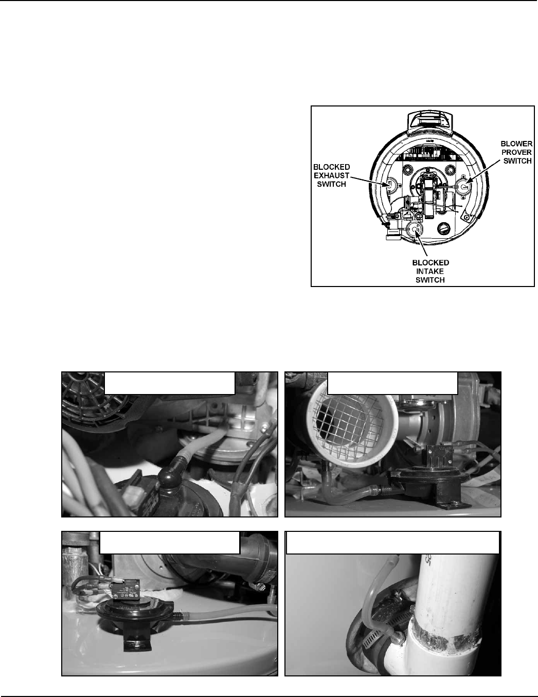
The water heater covered in this Service Manual is factory equipped with three air pressure
switches. These switches are used to provide verification or prove electrically that the
blower is running and that the vent and intake air pipes are not blocked or restricted. The
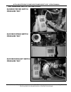
switches are located on the top of the water heater as shown in the illustration below.
These switches monitor air pressure through plastic sensing tubes from three different
sensing ports on the water heater. The Blower Prover switch monitors pressure from the
blower’s outlet flange. The Blocked Intake switch monitors pressure from the blower’s intake
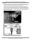
air connection fitting. The Blocked Exhaust switch monitors pressure from the exhaust/vent
connection elbow on the bottom of the water heater. See the images below.
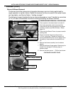
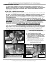
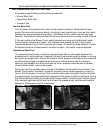
TOP VIEW
FRONT
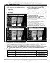
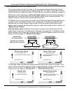
• BLOWER PROVER SWITCH
normally open contacts - close on a rise in pressure
• BLOCKED INTAKE SWITCH
normally closed contacts - open on a fall in pressure
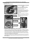
• BLOCKED EXHAUST SWITCH
normally closed contacts - open on a rise in pressure
All switches have SPST(single pole single throw) contacts.
Blocked Intake Switch
Blocked Exhaust Switch Blocked Exhaust Switch Sensing Port
Blower Prover Switch