


60
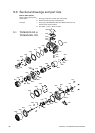
0040
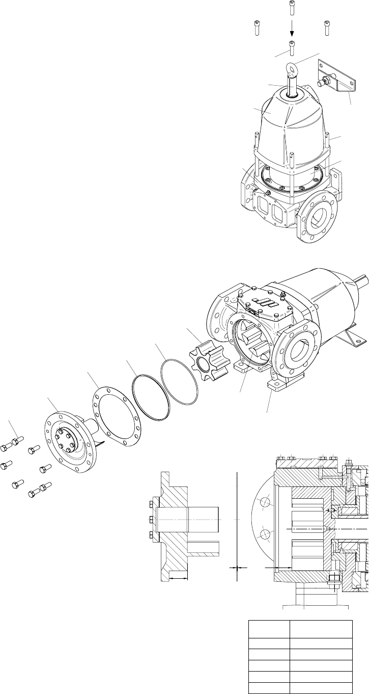
0600
8120
8110
8100
4000
1410
1700
A
S B
0702
1400
Tool
8330
8450
0701
0010
A.0500.551 – IM-TGMAG/02.00 EN (02/2008)
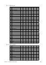
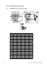
TG MAG
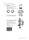
Axial clearance C
[mm]
15-50 0.120 – 0.200
23-65 0.125 – 0.215
58-80 0.150 – 0.250
86-100 0.165 – 0.275
185-125 0.190 – 0.320
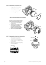
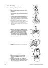
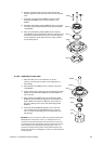
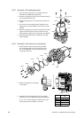
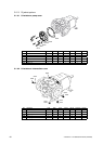
4.3.5 Assembly of the bearing bracket
1. Place the pump vertically on the workbench with the
separation can (8330) pointed upwards.
2. Screw the 4 guiding pins (tool) into the threaded holes of
the cap head screws (1410).
3. Screw a lifting eye bolt into the shaft end of pump shaft
(0702).
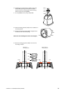
4. Use a crane to fit the bearing bracket (1400) over the
guiding pins to the intermediate cover from the top (see
picture).
5. Remove the guiding pins and fit cap head screws (1410).
Tighten cap head screws (1410) crosswise to fix the
bearing bracket (1400) to the intermediate cover (8450).
6. Mount bearing bracket support (1700) to the bearing
bracket (1400).
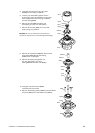
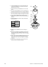
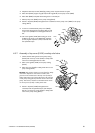
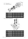
4.3.6 Assembly of the front-pull-out assembly
1. Check that the contact faces and O-ring chamber
are not damaged and free of dirt. Check the condi-
tion of O-ring (8120), in case of doubt replace the
O-ring with a new one.
2. Measure the distances as indicated
on the sketch.
3. Calculate the required thickness of the shim (8100)
between pump cover (4000) and pump casing (0010).
S = A – B + C. Axial clearance C between rotor shaft
(0701) and pump cover (4000) – see table.
Lifting eye bolt