


58
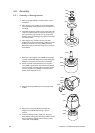
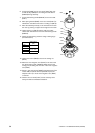
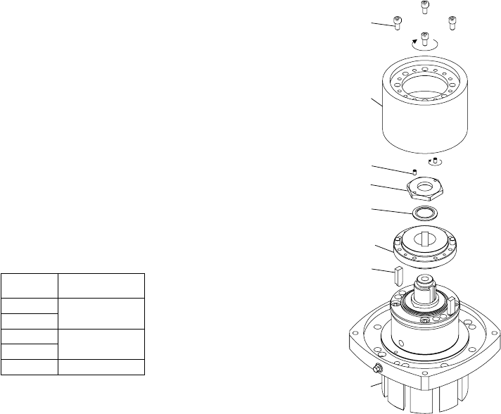
8490
8310
8520
8510
8500
8350-D
8400
0701
8350-B
A.0500.551 – IM-TGMAG/02.00 EN (02/2008)
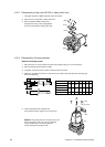
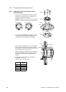
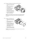
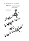
6. Fit the keys (8400) into the rotor shaft (0701). Be care-
ful that the keys (8400) are not hitting the shaft sleeve
(8350-B) during assembly.
7. Fit rear axial bearing holder (8350-D) on the rotor shaft
(0701).
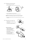
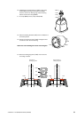
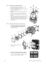
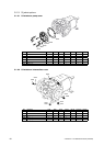
8. Place spring washer (8500) on the rotor shaft (0701) as
indicated on the sketch and screw on locking nut (8510).
9. Place the assembly vertically on the work bench and lock
the rotor by pushing a copper bar through the rotor teeth.
10. Tighten locking nut (8510) until the shaft nut makes
contact with the axial face of the rear axial bearing holder
(8350-D).
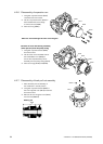
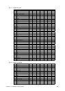
11. Check the axial bearing clearance using a feeler gauge
(see table below).
TG MAG
Axial clearance
[mm]
15-50
0.11 – 0.13
23-65
58-80
0.13 – 0.15
86-100
185-125 0.15 – 0.18
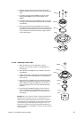
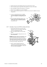
12. Tighten set screws (8520) to secure the locking nut
(8510).
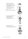
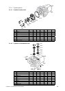
13. Mount the inner magnetic rotor (8310) on the hub of the
rear axial bearing holder (8350-D). Make sure that the
locking pins are falling into the holes of the inner magnetic
rotor (8310).
14. Screw in cap head screws (8490) and tighten them (with
Loctite 243) crosswise with the specified torque (see
Chapter 3.21.3.1) to fix the inner magnetic rotor (8310)
on the hub.
15. Check if the rotor shaft (0701) can be turned by hand
evenly and without remarkable resistance.