


54
1450
1460
1440
1430
0702
0702
8610
8600
8320
1400
8620
1400
0702
8320
8620
8630
8620
A.0500.551 – IM-TGMAG/02.00 EN (02/2008)
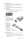
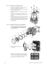
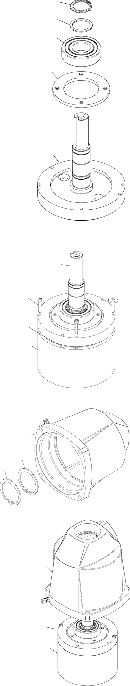
4.3 Assembly
4.3.1 Assembly of bearing bracket
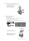
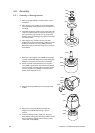
1. Place pump shaft (0702) in vertical position on the
workbench.
2. Place bearing cover (1430) over pump shaft (0702).
The countersunk-holes should point in the direction of
the flange.
3. Assemble ball bearing (1440) on the pump shaft. Use
a pipe and a plastic hammer and drive the bearing via
the inner bearing ring carefully over the pump shaft
(0702) until the inner bearing ring makes contact with
the shaft shoulder.
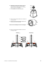
4. Place support ring (1460) over the pump shaft
(0702) and secure the ball bearing (1440) with circlip
(1450) on the shaft. The circlip (1450) should be
fitted under axial pre-load into the groove in the pump
shaft (0702).
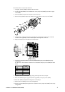
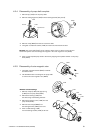
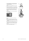
5. Mount the outer magnetic rotor (8320) on the flange
of pump shaft (0702). Make sure that the locking pins
(8600) are coinciding with the holes in the flange.
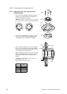
6. Screw cap head screws (8610) into the magnetic
rotor (8320). Tighten these cap head screws (8610)
with Loctite 243 crosswise with the specified torque
to fix the magnetic rotor (8320) on the pump shaft
(0702). (See chapter 3.21.3.1)
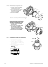
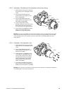
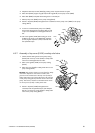
7. Mount both circlips (8620) into the bearing bracket
(1400).
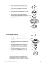
8. Support the pump shaft (0702) complete with
magnetic rotor (8320) and bearing in vertical
position.
9. Lower the bearing bracket (1400) over the pump
shaft (0702), pushing the ball bearing (1440) into the
seat in the bearing bracket until the bearing makes
contact with circlip (8620).