


61
4000
1020
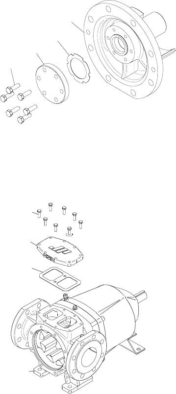
1000
1010
1080
0100
1090
0010
A.0500.551 – IM-TGMAG/02.00 EN (02/2008)
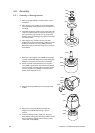
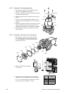
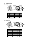
4. Adjust the thickness of shim (8100) by peeling of the required number of layers.
5. Place shim (8100), support ring (8110) and O-ring (8120) on the pump cover (4000).
6. Place idler (0600) complete with bearing bush on the idler pin.
7. Mount pump cover (4000) on the pump casing (0010).
8. Screw in tap bolts (0040) and tighten them crosswise to fix the pump cover (4000) on the pump
casing (0010).
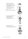
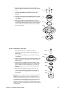
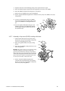
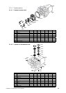
9. In case of a stainless steel pump cover (4000),
check if the sealing faces around the idler pin and
on pin cover (1000) are not damaged and free of
dirt.
10. Use a new gasket (1020) before fixing pin cover
(1000) on the pump cover (4000) with tap bolts
(1010). Tighten tap bolts (1010) crosswise with
the specified torque.
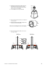
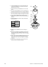
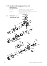
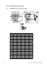
4.3.7 Assembly of top cover (0100) or safety relief valve
1. Check that the sealing faces of the pump casing
(0010) and on the top cover (0100) or safety relief
valve are not damaged and free of dirt.
2. Place a new gasket (1090) on the pump casing
(0010).
3. Place top cover (0100) or safety relief valve on the
pump casing (0010).
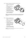
Remark: The position of the top cover (0100) or safety
relief valve depends on the sense of rotation. The
grooves in the contact face of the top cover (0100) or
safety relief valve must connect the hole in the top face
of the pump casing (0010) with the suction side of the
pump. The sense of rotation is indicated with an arrow
on the top cover (0100) or safety relief valve.
4. Screw in tap bolts (1080) and tighten them
crosswise with the specified torque (see Chapter
3.21.3.1) to fix the top cover (0100) or safety relief
valve on the pump casing (0010).