


10
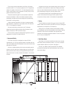
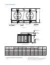
/ Inlet Piping Plan /
G
BASE OF
TOWER COL.
INLET
C
L
B DIA. FLOW CONTROL VALVE
AND CROSSOVER PIPE
REWO4
LEDO-
-0'
LLE#REP
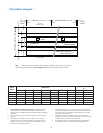
SNOISNEMI$
! " # $ % & '
q
q
q
q
a q a q
a M6 q
a M6 q
a 6 q
a 6 q
a 6 q
q
q
q
q
a q a q
a M6 q
a M6 q
a 6 q
a 6 q
a 6 q
q
q
q
q
a q a q
a M6 q
a M6 q
a 6 q
a 6 q
a 6 q
q
q
q
q
a q a q
a M6 q
a M6 q
a 6
q
a 6 q
a 6 q
q
q
q
q
a q a q
a M6 q
a M6 q
a 6 q
a 6 q
a 6 q
q
q
q
q
a q a q
a M6 q
a M6 q
a 6 q
a 6 q
a 6 q
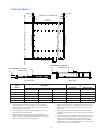
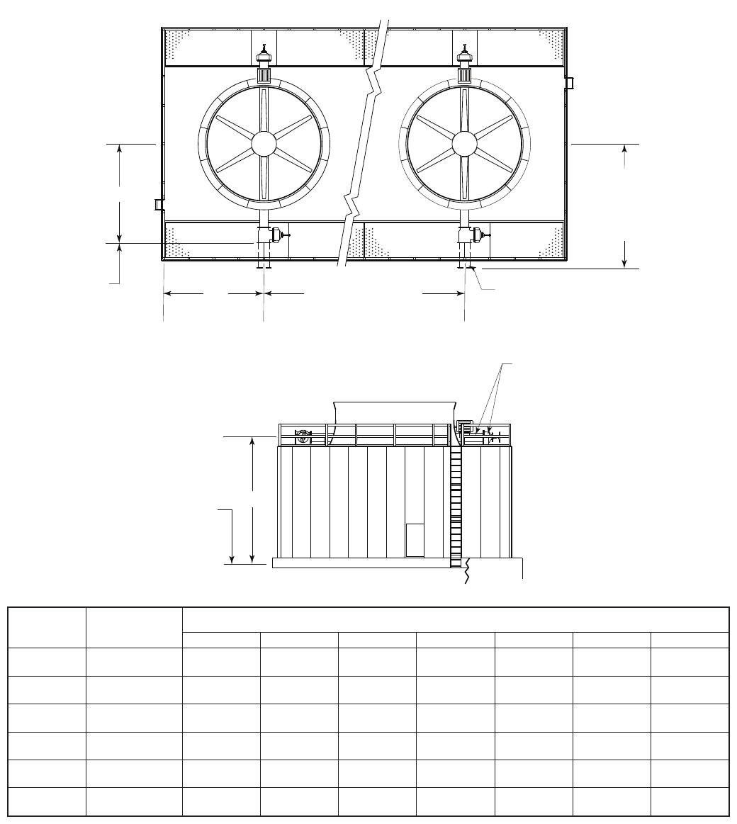
1. Use this bulletin for preliminary layouts only. Obtain current
drawings from your Marley sales representative.
2. Pumping head contributed by the tower is static lift shown
on page 7. Actual pumping head will vary according to tower
circulating GPM. Total pumping head will be furnished at time of
proposal.
3. If your application requires a bypass system, recommended
location is through tower endwall into plenum area. Review of
the system by Marley engineering is required.
4. Marley piping terminates at face of a cast iron at face ange.
Bolt circle conforms to class 125 lb. ANSI B16.1 specications.
5. Supports on tower for crossover piping are furnished by Marley.
Do not support the riser’s dead load or operating load from the
tower. Do not brace the riser’s seismic or thrust loads against
the tower.
6. On Models 1611 through 1641 with a 32 or 3200 Geareducer
the inlet diameter must be 20″.
D TYPICAL MULTICELL
FACE OF
A DIA.
INLET FLANGE
C
F MINIMUM
E
FAN
TOWER
C
L
COL.
C
L
TOWER
C
L
INLET
C
L
C
L
INLET
PIPING SHOWN WITH
HIDDEN LINES IS BY OTHERS