


Page 19
GV100W BOILER
INSTALLATION & OPERATING INSTRUCTIONS
If the computed rate deviates by more than 5% from the rated
input value of the unit adjust the gas valve pressure
accordingly. Do not adjust the manifold pressure by more than
5%. If a proper rate cannot be maintained without adjusting the
manifold pressure beyond the 5% limit, the main burner orifices
must be replaced. If the input rate is too low, go to the next
larger size orifices. If the input rate is too high, go to the next
smaller size.
Propane Gas
The input rate for LP units is factory set based on the orifice
size. The manifold pressure must be set at 10" WC and the
#54 burner orifices used unless the unit is to be derated for
altitude.
CAUTION: Never increase the input to the boiler above that
for which it is rated. Doing so can cause premature failure
of the boiler.
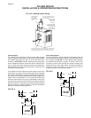
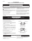
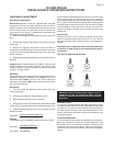
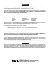
FIG. NO. 18 Main Burner Flames
WARNING: Yellow, flooating flames indicate a lack of
combustion air. Do not operate the boiler until the
problem is solved or severe personal injury or death
may occur!
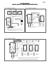
Low Water Cutoff
If the boiler is equipped with a low water cutoff device make
sure that the main burners will NOT light when the boiler has
no water in it. To check, turn the boiler off, close the valves in
the water supply and return lines and drain the boiler. If the
boiler’s main burners light shut the boiler off immediately and
correct the problem.
Thermostat Adjustment
For a thermostat that employs an adjustable heat anticipator,
adjust the anticipator to match the current measured in the
thermostat circuit. An increased anticipator setting may be
necessary if the unit cycles frequently. If the room temperature
over-shoots the thermostat setting, reduce the anticipator
setting.
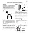
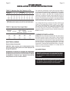
CHECKING & ADJUSTMENT
Gas Pressure Adjustment
Natural Gas Optimum results are obtained when the boiler
is operated at its full input rating, with 3.5 in,
89 mm
, WC of
manifold pressure. The manifold pressure should not be more
that 5% off this value. The gas valve pressure regulator has
been preset at the factory. If adjustment is necessary the
following steps must be followed.
1. Attach a manometer to the pressure tap on the gas valve
body.
2. Remove the regulator adjustment screw cap from the gas
valve body.
3. Rotate the regulator adjustment screw clockwise to
increase the manifold pressure, counterclockwise to decrease
it. Never force the regulator adjustment screw or the gas valve
will be damaged!
4. Replace the regulator adjustment screw cap and pressure
tap plug.
Propane Gas A manifold pressure of 10.0 in,
254 mm
, WC
must be maintained for proper operation of the boiler. If the
manifold pressure is off by more than 5% adjust it according
to steps 1 through 4 above.
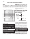
Input Rate
Gas appliances are rated based on sea level operation with no
adjustment required at elevations up to 2000 ft,
610 m
. At
elevations above 2000 ft,
610 m
, input ratings should be
reduced by 4% for each 1000 ft,
305 m
, above sea level. Check
the input rate as follows:
Natural Gas
1. Turn off all other gas appliances that use the same gas
meter as the boiler.
2. Call the gas company for the gas heating value.
3. Start the boiler and let it run for 15 minutes.
4. Using the gas meter and a stop watch, clock the time that
it takes to burn 10 cubic feet of gas and divide the time by 10.
5. Insert the heating value and the time, in seconds, into the
following formula.
Input Rate =
Heating Value(Btu/ft
3
)(3600 s/hr)
Flow Rate(s/ft
3
)
Example:
If the heating value = 1000 Btu/ft
3
and the flow rate = 36 s/ft
3
Input Rate =
(1000 Btu/hr)(3600 s/hr)
36 s/ft
3
Input Rate = 100,000 Btu/hr
YELLOW TIPPING
(MARGINAL)
LIFTING
(TOO MUCH AIR)
NORMAL
(HARD FLAME)
YELLOW FLAME
(TOO LITTLE AIR)